Do you want to be a wheelwright?
by Dave Booth based on Sid Stubbs’ original articles (Sid’s text is in italics)
Photographs by Dave Booth, drawings by Geoff Wilson (click on drawings for large printable versions)
Wheel making is something of a tradition at Manchester Model Railway Society. It started just after the Second World War, in a period when materials for hobbies were not readily available and when the hobby was essentially based on toys which, by present day standards, left a lot to be desired both in accurate modelling and in good, smooth running.
At that time a small group of modellers within the MMRS, led by Alex Jackson, started to push out the boundaries of the quality of modelling. Most were professional engineers of one sort or other but their binding force was a desire to improve the running and the scale accuracy of their models. Names that immediately come to mind as members of that group are: Ross Pochin, John Langan, Norman Whitnall, Sid Stubbs. There were others but this is not the place to list them all, suffice to say that many who read this will have heard of, or read an article by, one or other of that group.
It was Sid Stubbs who accepted the challenge of designing an accurate model railway wheel and his work produced a standard of wheel which, apart from being better than anything available at the time, will run without problem on present-day 4mm finescale layouts, gauge being unimportant as long as the track standards and wheel back-to-back dimension are adhered to.
Sid consulted the relevant British Standards Institution’s specification that related to full size railway wheels of the day. He turned tyre profiles of exactly 1:76.2 of the full size dimensions in that specification, and wheels with such tyre profile were tested on the 18mm gauge track on which this group had standardised. They ran well but not as well as hoped, so Sid tried again but this time he used those dimension in the BSS which were listed for wheels that had reached maximum allowable wear and were due to be re-profiled. This wear does not occur on the toe of the flange, only on the coning, and it has the effect of making the flange minutely deeper.
This new form gave running which was very acceptable to the group and became the standard flange form for their wheels. Someone christened it “The Manchester Profile” and that is how it is known to this day.
Turning any tyre form with standard lathe tools demands, possibly, above average skill at driving a lathe. To simplify wheel making for his friends, Sid devised a form tool which would consistently cut the desired shape and demanded little more skill than straight forward ‘turning to diameter’, plus the knowledge that using a form tool demands above normal power, low speed and plenty of coolant if cutting steel.
In the past Sid authored several articles that covered wheel making and were published in model railway press, notably Model Railway News of June and July 1959. It is because these articles are not readily available to modellers that it was decided that the information should appear on Manchester Model Railway Society’s web page but, because it is difficult to overcome copyright problems – (how can we ask permission of a magazine which is no longer published?) – this piece has been specially written for the web and, with Sid’s permission, uses some of his original wording.
 In the first part of his original article Sid talked about the lack of accurate wheels available from the trade. We have not included this earlier part because, over fifty years later, it no longer applies. However one of the diagrams from that section is included here.
Figure 2 (numbering is from the original article) shows some important typical dimensions of standard driving wheels which are useful to have to hand if you do decide to make your own all metal wheels.
The introduction of plastic injection moulding in more modern times has led to an excellent and large selection of locomotive driving wheels, with metal tyres bonded to a plastic wheel, but you may still wish to face a challenge and if you build chassis of split-frame, split-axle design, then solid metal wheels become very desirable.
Before you read too far and get all excited about your future at making extremely acceptable wheels for your models, can we add a word of warning. Many of us modellers have a lathe and are quite capable at simple turning jobs: turning to a given diameter, facing to a given length, centre drilling and drilling through, possibly taper turning and even free-hand turning, but many have not met the job of using a form tool.
The problem with any sizable form tool is that the cutting area of the tool is very much greater than that of the more usual lathe tools and consequently needs greater power and develops more heat. You almost certainly know that using a parting-off tool demands a differing approach to straight forward turning. Well forming is even more demanding of low speed and high input power. If your lathe is one of the “table top” variety, with an ex-sewing machine motor or similar, then forget it! Something about the size of a Myford ML10 is probably the minimum size that will cope with making wheels in the way that Sid and his friends pioneered. No doubt there will be the odd genius who will tell us of ways around that problem but here we are trying to describe a simple method for modellers whose lathe skills fall a little short of “genius”.
It is the form tool that lowers the skill need. The form tool, used correctly, cuts identical forms time after time; just gradually feed the tool into the work and the full tyre profile results, all tapers, angles, radii and other dimensions exactly correct and identical to all previous and subsequent tyres. Without the form tool, then the lathe operator needs the ability to achieve all of that but via his own skills. With the form tool the operator needs only the ability to turn accurately to diameter.
So first off – obtain your form tool. Unfortunately we cannot direct you to a source of form tools for model railway wheels. We are unaware of any trader or society who retails such a tool but none the less we believe that they have been available, particularly for the P4 profile. If you cannot locate a source of tool with the profile you seek then it but remains to make one, or if your skill does not extend to that level find a friend who can do it for you. Sorry about that. If you wish to stretch your skills or if your skills already meet the required level then here, taken from Sid’s Model Railway News articles, is what you need to do.
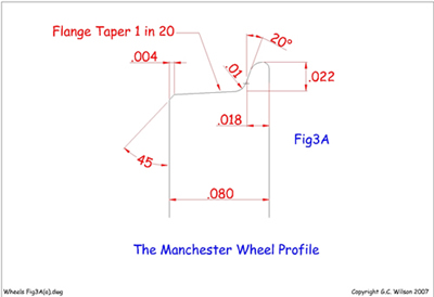 The wheel profile used is shown in Fig 3A and it is to near scale standards, but there is no reason why one or other of the recognised standards should not be used instead.
It is, however, very necessary to provide the 1 in 20 taper on the tread, the 20 deg angle on the flange face and the radius between flange and tread and at the top of the flange. Here lies the secret of good running.
 To proceed with manufacture of the tool take a piece of ⅝” or ¾” dia. silver steel bar and turn and part off a plain wheel with a 3/16” dia. bore, taking great care to bring the profile of flange and tread to a high finish by the use of sharp tools and a final polish with varying degrees of emery down to the finest grade.
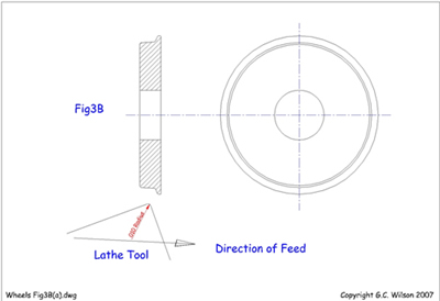
Fig 3B shows this wheel and also the shape of the tool end for turning the profile. The 1 in 20 taper on the tread is obtained by setting over the top slide and a fine file attends to the radius on the top of the flange.
 The wheel is then hung on a loop of iron wire through the bore and suspended from a pair of pliers in the fiercest flame of the gas stove or Bunsen burner, or placed inside a tin in a hot fire, until it becomes bright red hot. You cannot overheat it in any of these flames. Once red-hot, drop the wheel in a tin of cold water and it should become glass hard, so much so that if it is filed with an old file the teeth of the file will be damaged without affecting the wheel.
Mount the hardened wheel on a 3/16 “ bolt with a nut tightened on to trap the wheel against the bolt head and, gripping the shank of the bolt in the lathe chuck and running at top speed, polish the slight scale off the profile with emery and oil.
 Then bring the profile to a high finish with metal polish or lapping paste on the soft end grain of a piece of wood pressed hard against the rotating wheel.
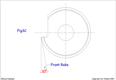
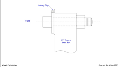
Finally grind a gash in the wheel as at Fig 3C to leave the profile exposed as a cutting edge of the shape of the wheel rim. Bolt the wheel to a piece of ½in steel, preferably using a high tensile Allen screw as at Fig 3d and, when the whole is mounted in the lathe toolpost, it becomes a turning tool.
Once more take the initial piece of ⅝” or ¾” dia silver steel and proceed to feed your newly made form turning tool into the bar of silver steel held in the chuck using the back centre, a slow speed and copious amounts of cutting oil. Again drill a 3/16 “ bore, part off and we have our final wheel profile tool, ready for use when mounted on the ½” square bar after hardening, polishing and grinding the gash as before.
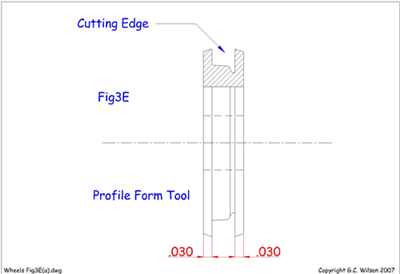 Fig 3E shows this tool and it will be seen that is has ‘prongs’ each side of the actual profile which settle the width of the wheel rim automatically. Note that the gash must be ground below centre to give front rake to the cutting edge. If you have no grinding wheel file in the gash before hardening and stone up the edge afterwards.
Keep dipping the tool into cold water whilst grinding the gash as heating will soften it.
Finally for 0 gauge the form tool should be about 1¼” diameter and the bore should be 5/16”
Having made the profile form tool, which will last a lifetime as it can be ground away right round the periphery to bring up a new cutting edge as it becomes blunt, wheel blanks can be machined in a ‘stick’ by feeding the tool in at intervals along a bar of brass, turning down to a given setting each time to ensure that all wheels are of the same diameter.
 Turn the bar between centres or support with the back centre if mounted in the chuck because the forming operation is quite heavy cutting on a small lathe. Use a slow speed if the lathe tends to ‘chatter’ and feed slowly but firmly. Use plenty of cutting oil if steel is used for O gauge.
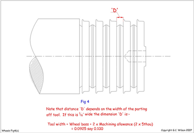
With the turned bar in the chuck and running truly (very important if the initial forming was done between centres) centre the bar with a Slocombe centre drill and run in a number 31 drill a little way, then part off the end blank between the formed profiles; drill and part off the next blank and so on.
Fig 4 shows the process so far.
Mount each blank truly in the chuck and face back to the edge of the rim, then turn under the rim and down to the boss, finally facing the boss which stands proud on the front of the wheel, but flush with the flange on the back. Turn round in the chuck and finish the other side. This part of the job has been left a little vague deliberately as the exact method depends so much on one’s own preferred method and equipment but, if a lathe is fitted for collets, which are a ‘must’ for a serious modeller, step chucks can be had which will grip wheel blanks absolutely truly. Failing these a ring can be machined in the chuck from brass with a recess to take the wheel tread exactly and, having put a pop mark on the ring against number 1 jaw of the chuck, it can be removed, split with a fine sawcut and, when replaced in the chuck with the mark against number 1 jaw, it can be tightened down to grip the wheels true whilst the back is turned. A similar ring, recessed to take the flange, holds the wheels for turning the front.
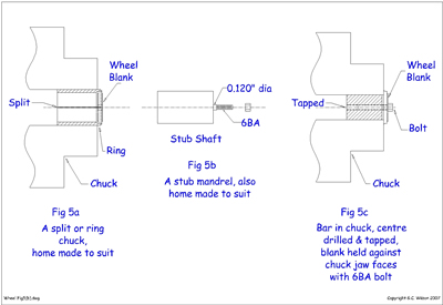 Alternatively, a small screwed stub shaft can be made on which to mount the wheel which is held by a nut, or finally a piece of bar can be gripped in the chuck with its end fractionally below the level of the chuck jaws and, having drilled and tapped a true hole in its centre, a 6BA bolt, with a short length of 0.120” diameter below the head, can be screwed in to bolt the wheel back against the face of the chuck jaws whilst you operate on the front. All these methods are made clear in Fig 5, and dimensions quoted are for 4mm scale. Revise for larger scales.
Having reached this stage, you should now have a series of discs of correct diameter with a tyre/flange profile, and faced front and back for both tyre and centre boss. The truly boring bit now has to follow; the spokes need fretting out. Sid and his friends fretted around driving wheel balance weights too but you may consider that simply fretting all spokes and then adding separate balance weights later is an easier approach – some of us do! – and it is of course what happens with trade supplied wheels. However let us carry on following Sid’s method.
Drilling for the spokes
It is necessary to drill a series of holes immediately beneath the rim and corresponding in number to the number of spokes in the wheel. It is also necessary to make the holes follow the contour of the balance weights. Note that, since the holes at the balance weights are drilled nearer to the centre of the wheel, they will be smaller as the space between the spokes becomes less. The drill size for the holes is obtained by measuring the space between adjacent spokes from a good scale drawing or by calculation.
In the latter case, make a rough estimate of the drill diameter, measure the diameter under the rim of the wheel and deduct the drill diameter, as estimated, from this figure. This gives the pitch circle diameter of the circle of holes to be drilled and this figure, multiplied by π (3.142) gives the circumference of the circle on which the holes are drilled. From this figure, take away the total thickness of all the spokes noting that real spokes are only about 1¼” thick at the rim although this figure varies and the actual loco being modelled should be checked. For 4mm scale this makes the spokes about 0.017” thick, i.e. less than ½mm; for 7mm scale 0.3mm (1/32” bare) and for 10mm scale 0.042” (1mm full). These figures will surprise many modellers and one well respected modeller, faced with such fine spokes, promptly dubbed the wheels ‘bicycle wheels’ but the details are correct and this only serves to show, once more, how, if one sees enough of the wrong thing the correct practice, when first met with, seems all wrong.
To return to the job in hand. Having deducted the total thickness of the spokes, we are left with the total value of the drill holes and this divided by the number of spokes gives the correct drill diameter. Select the nearest drill below this, or perhaps for safety, a size below that. You can always file out the drill hole when filing the wheel spokes later, but if the drill is too big, or a bit out of correct spacing, the resultant hole will not clean out, but will remain as a ‘half moon’ cut away in the spoke. Perhaps a sample calculation will make all clear.
Assume a 4mm scale wheel having a tread diameter of 21½mm (5ft 4½”). The under rim diameter scales ¾” (0.75”). The rough estimate of the drill diameter is 0.10” and deducting this from the under rim diameter of 0.75” we get a pitch circle diameter, on which the holes are drilled, of 0.65” which, multiplied by π becomes 2.042”. There are 17 spokes and if each is taken as 0.017” thick, they have a total thickness of 0.017 x 17 = 0.289” which must be taken from 2.042” leaving 1.753” to be divided into 17 drill holes. This gives a drill size of 0.102” and a number 38 drill is the nearest below at 0.1015”. To be on the safe side and to utilise a common size of drill select a 3/32“ drill measuring 0.0937”
The question of how to space and drill holes now arises. If the modeller is the fortunate owner of a dividing head for use with his lathe the matter is quite straightforward. Slap the wheels one at a time (or even several at a time) on the dividing head and drill the holes, but note that it is advisable to go round first with a short ‘Slocombe’ centring drill, following up with the normal twist drill. This prevents the holes ‘wandering’. Do not forget to shift the slide carrying the head when you come to the holes where the balance weights are and use a correspondingly smaller drill. It might be quicker to divide one wheel only and to use this as a drill jig, clamping the others to it in turn and drilling off the first one.
If a dividing head is not available, a drill jig can be marked out on the lathe by chucking a flat disc of steel and fitting a change wheel from the screw-cutting gears to the other end of the mandrel. This change wheel is selected to have the same number of teeth as the number of spokes desired or a multiple, i.e. a 20-tooth change wheel would give 20 spokes by indexing one tooth at a time or 10 spokes by indexing two teeth at a time; a 60-tooth change wheel would give 12 spokes (five teeth) or 15 spokes (four teeth) and so on.
Ideally, for use with this method, a spring-loaded plunger to fit between the change wheel tooth flanks, and thus position it accurately, is desirable and my own lathe has one fitted to the reverse stud bracket, but the change wheel banjo plate could just as easily be utilised. Failing a special plunger, a pointer, set close to the change wheel teeth would serve just as well and this suggests still another use for the scribing block.
Whatever method is used to index the change wheel the procedure on the disc for the drill jig is the same. Locate a scriber in the toolpost at centre height with the point facing the disc and, bringing the scriber point in contact with the face of the disc wind the cross slide across the face and thus scribe a line radially on the disc. Index the change wheel to give the required division and repeat the scribing process until a set of scribed lines, equally spaced round the disc, and equivalent to the number of spokes, has been marked. Next, set the scriber to touch the disc at a radius from the centre equal to the radius of the circle on which the holes are to be drilled and rotate the lathe a full revolution so that a circle is scribed cutting all the radial divisions. Finally, drill a hole in the centre of the disc, equal to the bore of wheel blanks. This is to take a screwed locating bolt with which the blanks can be positioned relative to, and bolted to the newly made jib. All that remains is to centre pop, most carefully, the intersections of the scribed lines and the circle but do not forget to move inwards a bit from the circle where the balance weights are to come. Now drill the disc at each centre pop using a ‘Slocombe’ centre drill to begin with and opening out with the final drill last. Each blank is then bolted to the jig and drilled from it.
The workshop at Dean Hall – the MMRS clubroom – includes a profile milling machine and rather than carry out the indexing process described above, Dave Booth uses that profile miller and a CAD programme in his computer to make a spoke-hole drilling jig. Firstly the CAD program is used to draw the wheel centre, the crank pin centre and the pitch circle for the holes, using Sid’s calculation as shown above but multiplying that diameter with the profile miller’s cutting ratio – 5:1 in this case. Then, taking account of the crank pin location, an array of radii, equal to the number of spokes is drawn. Where these each cut the pitch circle is the centre of each hole, but remember at five times the required dimension for the wheel. This drawing is then printed to card.
Using the profile miller, the card is mounted on the master platen and a piece of about 1/8” thick mild steel mounted on the work platen. A Slocomb drill (centre drill) is mounted in the cutting chuck and a pointer follower in the master chuck of the profile miller.
Next a centre pop is drilled into the mild steel work piece at wheel centre, crank pin centre and each spoke hole centre.Using a pillar drill, these centre pops are opened to the required diameter, in Dave’s case, 3.1mm for the axle, (later to be taper reamed to accept 1/8” axles), 1/16” for the crank pins and to the calculated drill diameter for the spoke holes – see Sid’s calculations.
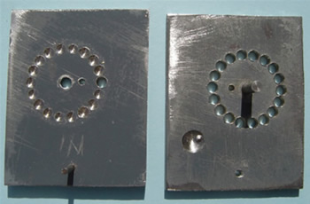
In use, this piece of 1/8” mild steel becomes the top of a drilling jig – see photo – into which the wheel blank is clamped for drilling. Very simple, very accurate, little skill needed, but requiring a computer with CAD programme, and a profile miller, so not available to all.
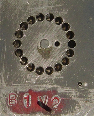 Left – B1 jig
Below – A different jig, but showing the two parts separated ready to receive a wheel blank for drilling.
Back to Sid again:
Marking the spokes and fitting the cranks
 Having drilled the blanks, the spokes require marking out on the face of the blank to provide lines to which one can cut when sawing out.
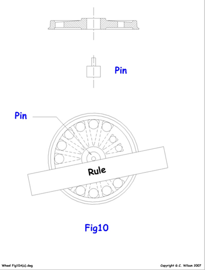
Fig 10 shows a pin turned to fit into the bore of the wheel blank and having a small extension equal in diameter to the spoke thickness. The pin is placed in the bore of the blank which is laid on the bench with the face, and the pin extension, uppermost. A steel rule can then be held with its edge against the pin extension and against the edge of each drilled hole in turn and the spokes scribed accurately.
Having marked the spokes the balance weight shape can also be scribed and the cranks sweated into position against the turned bosses using plenty of solder or solder paste to get a good fillet and to give the impression of a casting.
These cranks should be of such a thickness that they stand well proud of the boss when they are soldered on so that they may be filed down level with the boss leaving no indication that they are separately applied. The fitting of the cranks is left to this stage so that they may be located accurately relative to the balance weights and to the spokes themselves.
Cutting out the spokes
For this operation to be effected in 4mm scale, a piercing saw frame and metal cutting fretsaws are needed; larger scales will be ignored for the moment.
The fretsaw blade is loosened at one end of the frame, the wheel blank threaded on, the blade then tightened up and the vee-shaped piece between the spokes is sawn out. The saw is loosened and passed through the next hole and so on right round the wheel.
Use the familiar vee-shaped sawing table as for fretwork, take things easily; sit down to the job and use a medium blade, not the coarsest and not the finest. When the balance weights are reached, the vee sawn out will be smaller, and the vee will not be as deep nor as pointed at the sides and apex of the crank. (Note added for web publication: this assumes that you have decided to have a solid balance weight).
It is this sawing job which seems to deter most people, who imagine that one must be a super craftsman with infinite patience to tackle such a job. Nothing could be further from the truth. Six 4mm wheels in brass can be cut quite easily in one evening, without breaking a saw, although it is worth changing the saw every so often as it is slow job cutting with a blunt one!
The well known ‘Eclipse’ piercing saw blades and frames are ideal for this job and are readily obtainable at most good tool shops, but here I must add the usual disclaimer. A normal fretsaw frame will serve, but it is not really stiff enough for metal and one can expect more broken saws and frayed tempers.
Whatever cutting out methods are used, cut as near as possible to the scribed line to avoid too much subsequent filing, but be careful not to go over the line on to the wrong side, or bad spokes will result.
The next section covered filing of the spokes and balance weights. You may decide not to include balance weights at this stage, so you are left the decision of how much of this you will actually follow.
It but remains to finish the spokes and balance weight profiles by filing. This is done in the vice and is a sitting down job with the eyes fairly close and level with the work. Fibre vice jaws are advised, otherwise the constant clamping up of the jaws as the wheel is reset for each spoke will damage the finish on the edge of the wheel rim beyond repair.
Dave Booth departs from Sid’s method here.
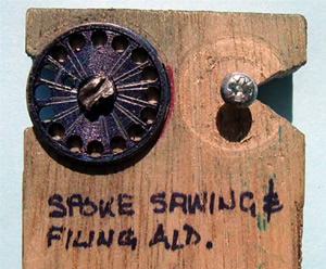
Dave made a holding jig, in every way similar to the familiar vee-shaped sawing table as for fretwork described by Sid, but in this case a half-inch, No.4 gauge, round head woodscrew through the wheel axle hole, is used to clamp the wheel to the saw table.
In this case the screw is repeatedly loosened and tightened in order to reposition the wheel for the next spoke; any damage is unlikely. This modified saw table is also used by Dave at the spoke sawing stage, described earlier in Sid’s words.
The original article next went on to discuss file selection but when Dave started to make wheels, he found difficulty in getting files which would go into the space between spokes, particularly on smaller wheels. The solution was to buy a pack of cheap needle files, market stall rather than high class tool shop, and grind the back and edges away, leaving just one cutting face on a very slim ‘blade’ of a file. These files are retained away from proper, good quality files, and used solely for wheel fettling.
Sid’s recommendation was: for 4mm wheels in brass, 14cm or 16cm needle files are used, but for 7mm or larger, small size normal hand files can be introduced into the space between the spokes and having a coarser cut than needle files the speed up the work. For 4mm work use a medium to coarse cut for shifting the metal, and a fine cut for finishing.
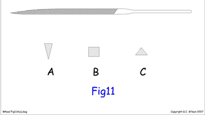 By far the most useful file is the knife file as shown in section at Fig 11. It is as well to grind the back of this file lightly to give a good edge with the sides and to ensure that it has an equal angle with each side, otherwise difficulty may be experienced in getting into the corners where the spoke joins the rim.
To file the underside of the rim a square section file proves best as at B in Fig 11.
Be careful if tempted to use a triangular file C as it tends to cut sideways into the spokes.
Do not forget to cut down well into the root of the spokes, using the edge of the knife file and remember that the distinctive shape of the balance weights is created at this filing stage. Do not try to file a vee section spoke but remember this section is provided on commercial wheels to enable the stamping or die-casting to draw easily from the die whilst, at the same time, the apex of the vee being at the face of the wheel gives an illusion of thin spokes. In fact real spokes are roughly rectangular with rounded corners when taken in cross section, the greatest dimension of the rectangle being from front to back. Sometimes this rectangle becomes nearer to an ellipse but never by any means a triangle. Therefore keep your file square across the wheel when filing the spokes and balance weight. Finally take the sharp edge off the spokes on the wheel face-side, using the tip of the file to scrape, as much as cut, as it will be found very difficult to get a file in place to file a radius, especially near the spoke roots.
You now have a number of wheels which look just about finished but Sid, in his article, offered some further guidance: the wheels can now be put on a bolt, nipped up between a nut and the bolt head and spun in the lathe to give a final polish with emery and to knock off the sharpness of the spoke edges by this polishing.
 We did make mention of turning the profiles after drilling, when no form tool is available.
Here, the point of waiting until the drilling is done, is that the blanks can be mounted either on the mandrel at Fig 5B, or the bar at Fig 5C, with small bolts through the spoke holes screwed into tapped holes in the face against which the wheel rests.These bolts act as drivers in addition to holding the blanks in place.
This last paragraph will only apply to those modellers who consider they have the lathe driving ability to carry out the relatively advanced turning which use of a correct form tool makes superfluous. Turning the whole tyre form using normal turning tools rather than a form tool still sets up high torque forces on the wheel blanks; the extra screws through the spoke holes provide a reaction torque which allows the tyre to be turned without the blank slipping on the mandrel. If your lathe skills are so high as to allow you turning the tyre in this way, then you probably did not need to read this article!
Sid talks about an alternative method of making wheels that some people call the ‘star spoke method’. In this, a tyre is fitted onto a star formation where the star is formed of spokes grouped around the centre boss. One of our members, Bill Newton, has an excellent web page which shows this method and rather than show Sid’s much earlier work, we suggest that Bill’s present day methods and web page http://www.clag.org.uk/bill-newton1.html will be more beneficial.
Finally we must confess that things do not always go according to plan, or in the famous words of Blue Peter presenters, “Here’s one I made earlier” which had to be rejected.
Bibliography
Not a definitive list of articles which relate to model railway wheel making, but it covers several methods. If you add the web page about Bill Newton’s method then you have met examples of just about all the scratch-building routes. Mind you, one of our members, Norman Whitnall, had some wheel blanks produced by a friendly, neighbourhood investment caster, and while Norman had to provide a master, we’re not sure that that falls under the heading of scratch building!
- Making Spoked Wheels by S. Stubbs, Model Railway News, June and July 1959
- Locomotive Construction for TT Gauge by L. H. Brown, Model Railway News September 1959
- S Gauge Claughton by P. Holth, Model Railways November 1985
- Scratch Built Wheels by S. Hine, Model Railways June 1986
- Big Wheels by T. Watson, Model Railway Journal No.168