These notes were written by John Langan for a series in The Link during 1963
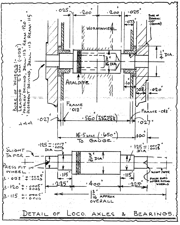
The general design of split axles, using Araldite as the joining medium, is as shown in the sketch. The procedure for making the axle stubs is to finish the female half of the axle complete, scribing a mark for reference of the position of jaw No.1 of the chuck. This stub and the unfinished male half are bonded and held together in a metal holding fixture whilst the Araldite is cured in the oven.

When the resin is set, the male end of the axle can be finish turned. This method has worked out very successfully on previous occasions, but this time I thought I would make the axles smaller in the body diameter, and also arrange for a vent hole to allow the joint to be filled with resin more readily.
Well, firstly the axles no longer fitted my holding fixture, and secondly the slit I had cut in the axle (see sketch) allowed the resin to ooze out just where the fixture should hold it, and the whole lot would have been glued solid. The slit idea was to avoid the alternative method of drilling a fine hole down the axle.
The fixture is quite an engineering job and a piece of equipment which you don’t undertake to make every week, so I was a bit annoyed at myself for not being able to make use of it. Rather than make another fixture, I decided to try the lazy way of holding the axles vertically by means of holes drilled into a wooden base.
The axles were quite true when put into the oven, but when taken out some were crooked like a dog’s hind leg and the others, though fairly true, had sunk down to give metal-to-metal contact between the two halves. Araldite is so good that there is no second chance – anyone want some bent axles for sharp curves?
I have now made a new lot of axle stubs which are quite plain (and no vents) to suit the existing fixture, and after bonding they will be turned down to the size required.
One final note. By careful assembly of the stubs it is possible to get sufficient resin into the joint without slits or other vents. This keeps the resin visible at only one position – at the joint.
Of course, if I ever make another holding fixture it will be made to suit the smaller finished size of axle. The female half would then be finished complete before bonding, as mentioned earlier.
Details of my glueing fixture for split axles. The holes in the fixture are drilled No.7 (.201″), so it will hold rod above this diameter true for curing the Araldite,

The details of the axles and the relative positions of the frames, wheels and bearings, with detailed dimensions for 4mm scale EM gauge:
Loco wheel bearings and sideplay
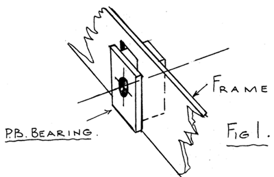 In the past I have made the main locomotive bearings of a rectangular shape to slide in the main frames, as shown in Figure 1. This is in accordance with full-size practice.
Recent model practice, however, has shown that turning the bearings from bar not only simplifies the making but also gives a more accurate spacing of the bearings in the frames due to the bore being central.
The original fear that the bearings would revolve in the slot of the frames has not proved any disadvantage.
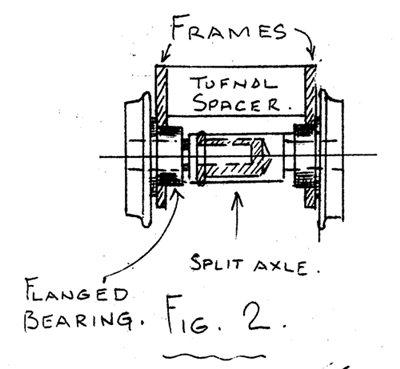 The arrangement of the bearings in the loco is shown in Figure 2.
From this it will be seen that the thickness of the bearing flange determines the amount of axle sideplay relative to the loco body.
When running on curved track some side play is, of course, required, the maximum amount being determined by the minimum radius of the track on the layout.
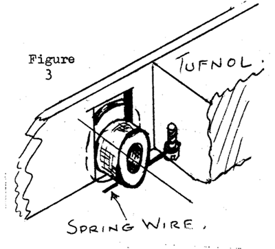 The wheels are prevented from dropping out of the frames by small wire clips fastened to the Tufnol spacing piece between the frames, as shown in Figure 3.
The largest wheelbase on my two locos is 8’3″, or 33 mm. on the model. For a track radius of 36″ the formula gives a sideplay of .023″. It must be remembered, however, that when on the straight there is a standard sideplay of .020″ between EM track and the wheel flanges. Without taking advantage of the fact that curved track should be over-gauge rather than otherwise, this 020″ play reduces the sideways movement to allow on the loco. So that in my case in theory; I need only .003″ play per side. With this condition, however, the wheels would be tight within the track and would not allow for any irregularities. For this reason a side play of .010″ each side of the centre line is allowed, and consequently the flanges of such bearings are .010″ thinner than the bearings of the “fixed” driving axle.
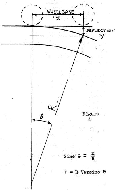 It is usual for the axle on which the worm wheel is fixed to have a minimum of sideplay and from this the amount of play in: the adjacent axles may be calculated.
With the driving axle on the centre line of the track the sideplay (from the centre on one side) may be calculated as shown in Figure 4.
Harry Townley pointed out that the locomotive should have more guidance around a curve than would be obtained from the sideplay indicated on my diagram. The leading wheels should help the locomotive round the curve. The amount of sideplay as described is only .010″ per side of the centre line and the point Harry raises, quite rightly, may be more important to watch on very small radius track and the larger scales.
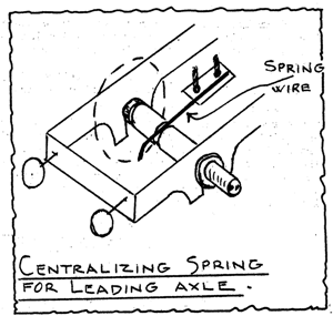
Should I run into trouble on this account I intend to try a simple centralizing spring as shown in the sketch. This should keep the wheels on the track and also tend to pull the front end of the loco round on curves. The spring will just touch the groove in the axle, without pressure. This will allow the wheels to sit nicely on the track without being too tight. I have tried a similar spring application to the pony trucks of my 2-6-2T loco and the result appears satisfactory so far.
Manufacture of the bearings
The bearings are, of course, made from bronze bar, and when working in this material always beware of swelling of the material at corners. This can give a false micrometer reading, so chamfer corners where possible, especially in holes. The sequence of operations is shown in Figure 5.
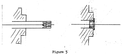 Skim to outer diameter.
- Turn bearing diameter.
- Drill 0.116″.
- Saw or part off. Reverse in chuck.
- Face flange to thickness
- Ream 0.125″.
- Bevel bore.
Arrangement of the bearings
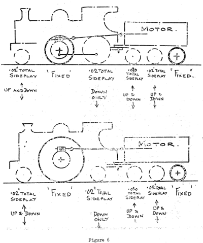 To achieve the best running conditions, i.e. track-holding properties with highest tractive force between the wheels and track, the aim should be to obtain a 3-point bearing between wheels and rails at all times.
This may be visualized by picturing the loco and tender as a rigid body with a pair of wheels at each end. These wheels should not have any side play, and so guide the body around the track.
Note the positions of the fixed wheels, and ignoring other considerations for the moment the wheels shown dotted could be imagined as not being required for our purpose.
However, the loco and tender not being a rigid body, but jointed as shown and with a universal joint between motor and wormgear, we have to support the engine and tender to meet this condition. In order to obtain maximum tractive effort from the loco, the weight of the motor and tender is allowed to bear down on to the back of the loco, pivoting from the rear wheels of the tender.
The back wheels of the loco may, therefore, only drop to take up inequalities in the level of the track, and normally the bearings are hard against the top of the slot in the frames. All other wheels are allowed up-and-down movement, and a light spring is applied to them to keep them to the track without taking any of the real load. Upward movement must be limited to a distance to equal the wheel flange depth, to avoid riding over the rail head.
It will be appreciated that we differ here from full-size practice, where all wheels, or rather their springs, are carefully adjusted on a multiple weighbridge, so that each axle bears its pre-determined share of the total weight of the vehicle. In the case of a model the difficulties encountered when you try to scale mass as well as size cause us, in effect, to concentrate on essential wheels, whilst endeavouring to ensure that all wheels are in. contact with the track all the time.
One final item as to the correct amount of play or interference, as the case may be, to allow when fitting metal parts together. Most engineering fits are based on the presumption that the hole is standard size. In model work you should ream the hole to size, as even a new drill may make an oversize hole. (For a drilled hole it is safer to check the actual size by making a dummy plug). We are mainly concerned with holes up to, say, ½” diameter, and the following tolerances should be applied.

| Hole | -0.00025″ | +0.00025″ | |
| Shaft | Force Fit | +0.0005″ | +0.0010″ |
| Drive Fit | +0.00025″ | +0.0005″ | |
| Push Fit | -0.00075″ | -0.00025″ | |
| Running Fit | -0.00125″ | -0.00075″ |