Making your own gearboxes
From articles in The Link (July, August 2008) by Geoff Wilson
Recently a long standing friend of mine died and left me a bequest of all of his model tramcars and this article is written about the seven which are 0 Gauge. They are all four wheel cars constructed with narrow rigid chassis and the wheels are somewhat undersized, being 18mm diameter OO gauge tender wheels Araldited on to 1/8th inch axles. The bodies and trucks were well worth retaining but the actual mechanisms left a lot to be desired. All have K’s motors and most have flywheels. I therefore decided that entirely new sprung chassis were required but using the existing motors and wheels.
I had one mechanism of the correct wheel base and was, therefore, faced with building at least six new mechanisms. This was a rather daunting prospect and I decided to look for ways in which I could fabricate, in the quantity required, common parts for all the models. Fortunately I had previously had to make some axle bearings so I had taken the opportunity to manufacture 64 of these at one time. This operation had entailed making some simple tools to ensure a quick repeatable manufacturing process. I seem to remember that I had taken two days to make the tools and two hours to make the bearings! However had I tried to make them individually I doubt whether I could have made them sufficiently alike to be of use and would have had to make considerably more than that to cover wastage. It turned out that one of the tools I made at that time was of great use in making some of the parts which form the subject of this article so that the original time spent on the tools was well worth it.
One common part which takes the most time to make and has an important bearing on the running of the models is the gearbox. I use Romford 30:1 or 40:1 gears and anything built should be able to take these gears and mount them and the motor to give the correct mesh.
There are of course gearboxes available using etched parts but these are generally designed for 1/8th axles for standard 4mm scale models. I have always thought these as a little flimsy and as I use 3/16th axles as used in 0 gauge they are not really suitable. The gear boxes I have built for previous tramcars have used 1/8th bearings and a screwed assembly, so I decided to look in detail at a design which follows my established pattern.
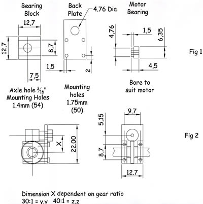 The design I evolved uses just four parts (not including the 10BA screws) two of which are the same, and which could be made in reasonable quantity.I use AutoCAD to produce the drawings so that I can try the parts for size and fit before cutting any metal. The drawing of the individual parts is shown in Fig 1 and the assembly is shown in Fig 2.The parts are 2 off side bearings, 1 off back plate and 1 off motor bearing. I built a total of 10 assemblies for the seven models plus spares.How I made the parts is shown below and is not necessarily the only way but may give others some thoughts on how they may tackle the same or similar jobs.I have included a number of photographs which should fill in any shortcomings in my description.
It might be appropriate at this point to make some general points about two aspects of making these gear boxes. The first is marking out, for which I use an old fashioned gramophone needle gripped in a pin chuck. I happen to be lucky to have a packet of these things which are not easy to get hold of. However an alternative is a darning or sewing machine needle mounted in the same way. In marking out I use a x3 magnifier clipped to my spectacle frame and look through this to mark out using a clear steel rule.
 The main advantage of using a needle of some sort instead of a conventional scriber is that it is much easier to see the exact place where a mark should be. I also use a similar arrangement to position the edge of parts in the lathe.
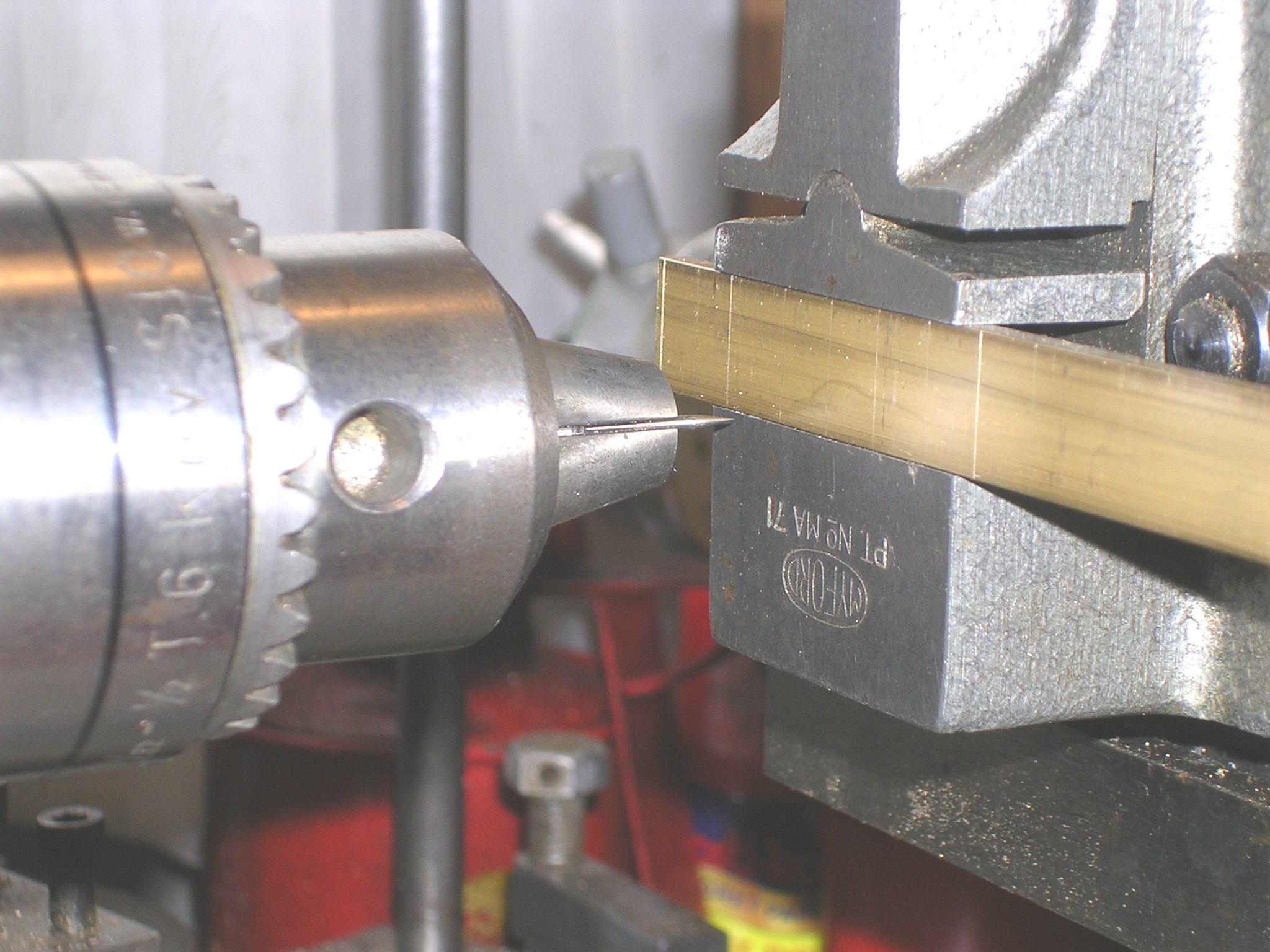
The photo shows a gramophone needle mounted in the chuck being used to determine the edge of the lower jaw of the machine vice. Again I use a magnifier clipped to my specs to examine the set up closely.
Do be careful when doing this and make absolutely sure that the lathe cannot start up when looking closely at anything mounted there. In the absence of a dial gauge it is possible to set the jaws of the vice exactly level in the same way.
Returning to the job in hand the first part I looked at were the two side bearings. As on previous gear boxes I used 1/8” by 1/2” hard brass flat. The first operation was to drill the axle holes which I carried out using the vertical cross slide mounted on my lathe. This operation and other milling operations could be carried out more conveniently on a small milling machine. Note that the jaws of the machine vice should be exactly horizontal to ensure that the holes are drilled at the same distance from the edge. I drilled out the 3/16th holes at 5/8th intervals along the bar and 0.295” (7.5mm) above the bottom.
On my lathe the various slides are marked in thousandths of an inch and having carefully set up the first position it was easy to move the strip exactly 0.625” to the next hole position. Each hole was first drilled with a centre drill and then opened out to 3/16th. I finished up with a length of brass with four holes drilled at exactly the same distance from the long edge. Note on the drawing that the axle hole is offset from the vertical centre of the bearing so that either gear set could be mounted without having to slot the back plate.
 I was limited by the width of the machine vice jaws and the travel of the cross slide to four holes per length and this governed my approach to the subsequent operations.
The interval between the holes depends on how you cut off the individual parts from the strip. Initially I used a hacksaw and therefore left a larger space between the holes than if I had cut them up on the lathe.
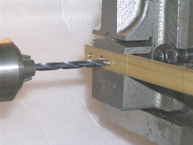
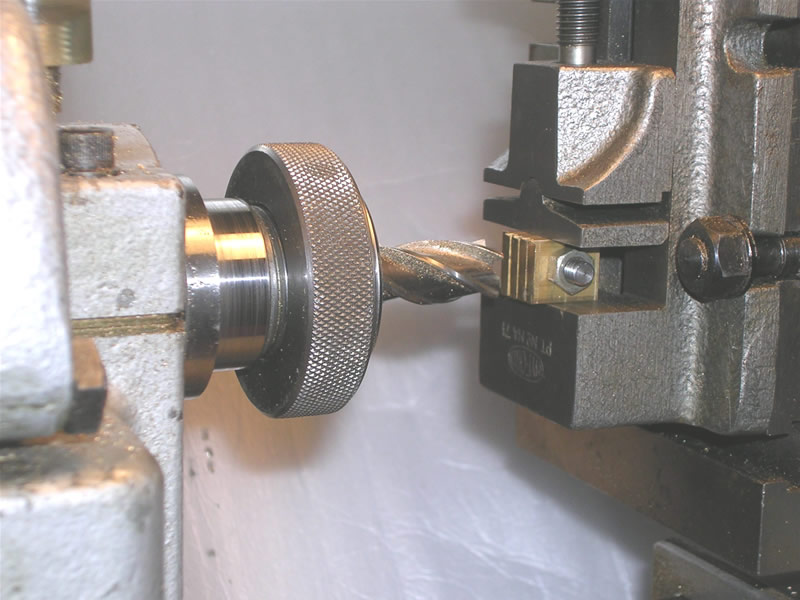
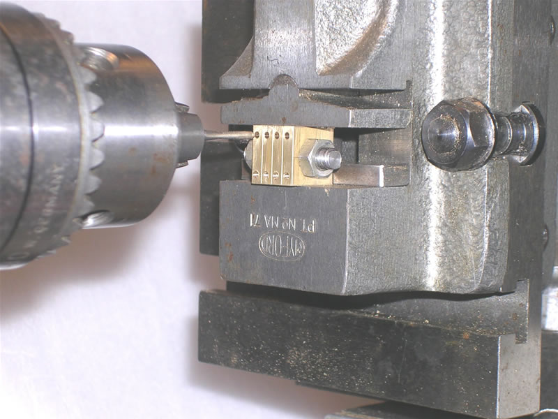
This operation I subsequently found I could carry out using a tool made to assist in the manufacture of the main bearings referred to above. This operation is easier and wastes less material and will be referred to later. Drilling the holes is shown in the photo.
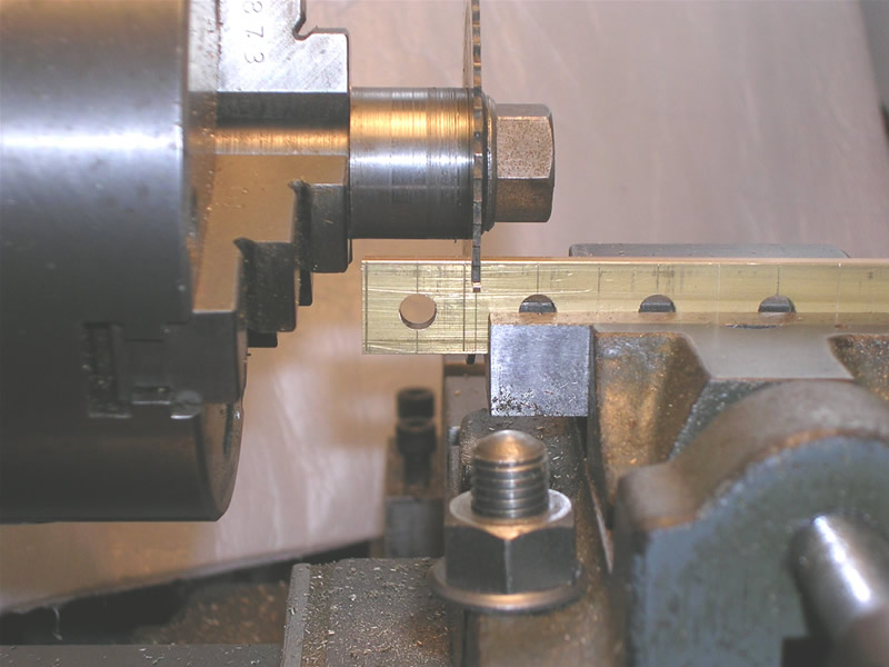 I then cut the strip up as shown in the photo so that the rectangles thus formed could be bolted together. You can see that I have marked out the position of the holes prior to drilling as a check to ensure I had moved the cross slide the correct number of turns of the handle to the next position when drilling.
I also scribed lines ¼” either side of the hole on the first position to act as machining guides on the operation following the cutting operation.
I then finish up with four rectangle of brass each with two nice straight edges from the original extrusion and two raw edges which have just been cut.
These two raw edges will, after further machining, be the top and bottom edges of the side bearings. These four pieces require to be clamped tightly together so that the raw edges can be machined to the dimensions shown on Fig 1. It is essential that the faces to be machined are parallel to the axis of the holes in which the axle will run. I made a short 3/16th diameter mild steel spindle, using material I use for axles, with a 2BA threaded portion at both ends. The four side bearings are then clamped together, between two nuts on this spindle, ensuring the non machined sides of the pieces are all perfectly in line.
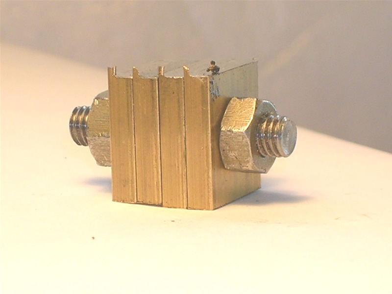 The side view of this is shown in the photo which clearly shows the sides cut in the last operation at top and bottom.
Clamp the assembly firmly in the jaws of the vice, ensuring that the first piece from the strip, with its scribed lines, is facing the operator. Make sure that the bearing pieces are exactly parallel with the axis of the milling cutter.
I use a square lightly clamped to the lathe face plate to ensure that the assembly is correctly clamped in the vice. This will ensure that the face that you are about to machine is at right angles to the sides of each side bearing.
 This photo shows the first face about to be machined and you can see the scribed machining line about 1/16th in from the raw edge on the first piece.
I machine with a light cut and many passes which is a reflection of the stiffness of the machine slide and lathe. In any case take light cuts as you get near (5 thou) to the final position.
Once this face is machined the clamped assembly can be turned over in the vice for the opposite raw faces to be treated likewise. This time you can use a simple parallel spacer i.e. a suitable piece of square or rectangular bar between the now machined face and the bottom of the vice to ensure that the two faces are machined parallel to each other.
 You should now have four side bearings clamped together.
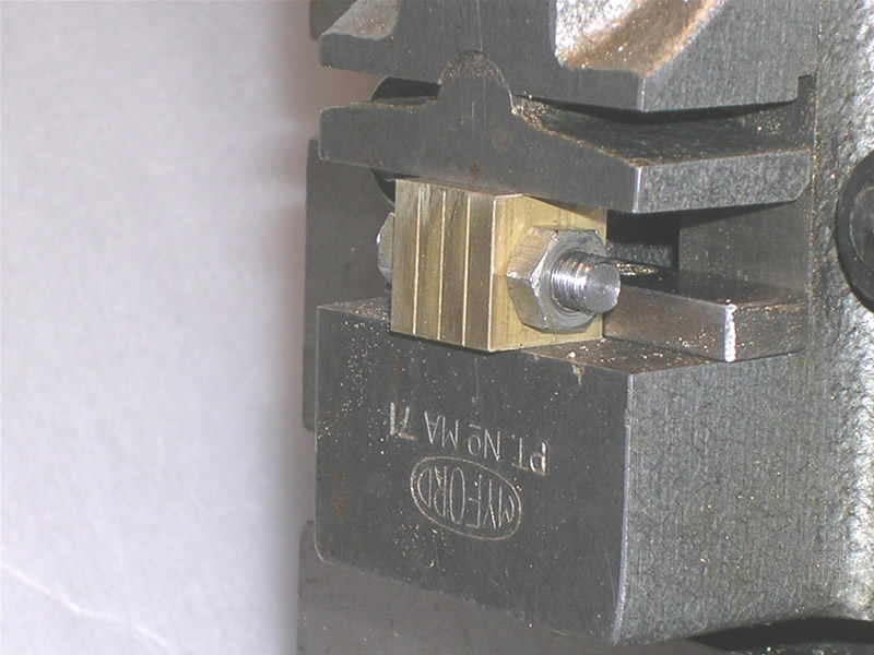
These can now be removed from the machine vice, turned through 90 degrees and reclamped so that the correct non machined side is facing the headstock end of the lathe as in the photo.
Note that the assembly is now clamped between the faces that have just been machined and that the next operations are carried out on the faces formed by the original extrusion.
I then determine the position of the lower left hand corner of the assembly using the needle in the lathe chuck mounted in the headstock. It is well worth taking some time over this and checking the position at least twice. Remember that the various slides of the lathe have backlash and that the only way to ensure repeat accuracy is to approach a position from one direction only. To repeat a measurement go back past the left hand corner in the horizontal and vertical directions and then approach the point again slowly turning the lathe handles in a clockwise direction. If you overshoot go back again to where you just started and try again. The reason I use the lower left hand corner is that the resulting operations add to the thimble readings of the cross slide and vertical slide and I find it easier to add the necessary dimension to the thimble readings than to subtract it.
Since the individual bearings are 1/8th thick the first position for a hole is 0.0625” from the back of the assembly and I therefore add that figure to the cross slide reading to get the horizontal position. The vertical position is 0.060” above the reading of the vertical slide and that is added to this measurement and these two movements give the position of the first hole to be drilled.
 The photo shows the start of the hole, drilled by the small centre drill, for the first screw hole.
I suppose I should have centre drilled, drilled out and tapped he hole with the lathe held in the first position but in fact I centre drilled all eight holes in succession. I centre drilled the lower row of holes first maintaining the vertical slide position for all of these and moving the cross slide exactly 0.125” for each of the subsequent holes.
I found it well worth writing out a table of both the thimble readings so that I could return to exactly the same positions for subsequent operations.
I added 0.343” to the vertical slide reading to give the position of the upper row of holes and then returned the cross slide back past the zero position. I then moved the cross slide back to the first position I had noted and centre drilled the first of the top row holes. The subsequent positions were those noted in the table.
I then drilled out the holes using a 54 or 1.375mm drill to a depth of 3/8th. My Dormer hand book supplied to me as an apprentice states that a deep hole is defined as one whose depth is more than three times the diameter. This hole is certainly deep by that definition and feed speed, via the leadscrew hand wheel, should be low and the drill withdrawn to clear the small brass chippings from the drill flutes. Use the previously noted readings to return the drill to exactly the same positions as the centre drilled holes.
 These holes can then be tapped 10BA using the tap held in the lathe chuck which is mounted in the headstock of the lathe. The chuck however should be loose in the headstock taper to ensure that, as the thread is cut, the chuck and tap are free to move towards the parts clamped in the lathe.
The thread is cut by turning the chuck by hand only. DO NOT use any other power. As the thread is cut you can take up the slack by gently operating the leadscrew hand wheel. However when withdrawing the tap, you will have to remember to reverse the process before the chuck is forced back into the headstock taper.
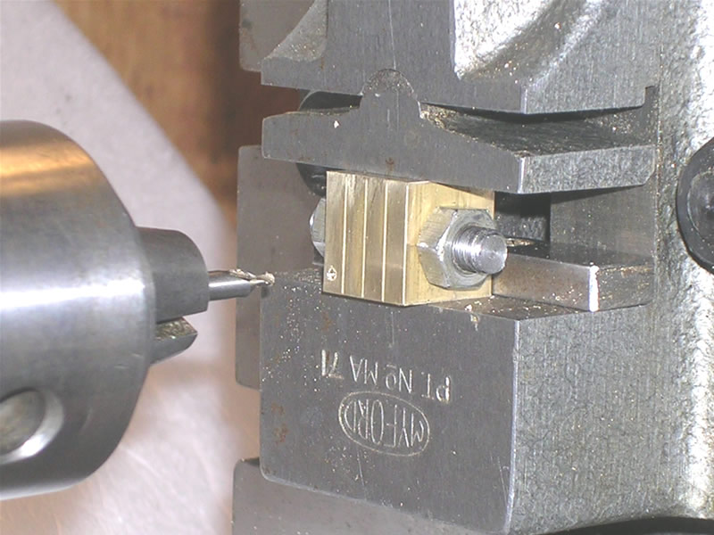
The photo shows the tap about to start on the first of the top row of holes, the bottom four having already been tapped.
When you have completed this tapping operation you can then unclamp the parts from the vice and release the studding holding them together. I find it best to hold them together in adjacent pairs using small wire and paper twists used on frozen food bags. Each pair can be fettled (cleaned up) using small files and emery when they are used in the assembly of the gear boxes.
The next pieces I made were the backplates on to which the bearings are to be mounted. For these I used ½ inch brass flats which are made of brass and are FLAT. Don’t be tempted to use brass strip which is cut on a shearing machine from a larger piece of brass sheet. The effect of the cutting action is to very slightly bend the strip making it definitely not flat.
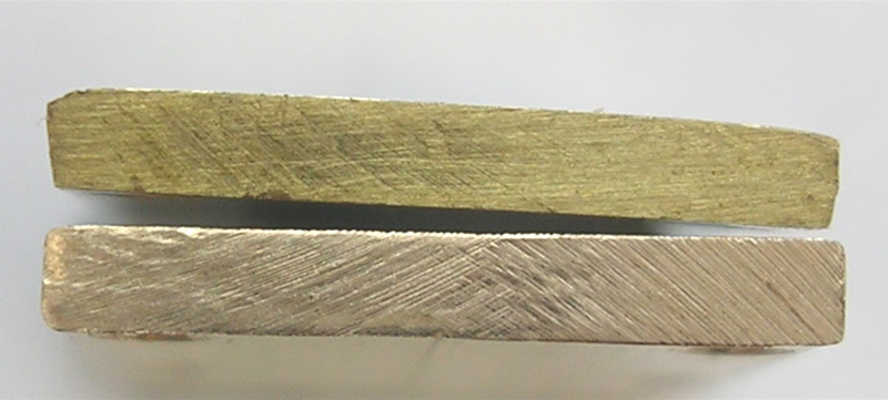 This is shown in the photograph where the curves introduced by the shearing action of cutting the strip is clearly seen on both the top and the sides of the upper strip. Contrast this with the straighter more rectangular outline of the brass flat, the lower of the two parts.
Though the difference may seem small it has a significant effect on the finished gearbox assembly and its consequent meshing and running.
It might be worth mentioning here that I have bought most of the material and fixings from Macc Model Engineering Supplies who I found on the internet when looking for brass flats. They operate a very quick and reasonable mail order service and have a good selection of materials, fastenings and other goodies if you can’t get there personally. My only connection with them is as a satisfied customer.
Before cutting the brass flat to length from the strip form in which it is supplied I scribe a line down the centre of the strip which I use later to show the centre line of the individual backplates. I did on some early ones mark each plate but it is considerably easier to get an accurate centre line over the whole length than one by one.
I then cut the brass flats up into pieces of the required length in the lathe in a similar manner to the way the bearing plates were cut up. The drawing shows that the length of each backplate as 22mm. The length is not critical and I actually cut mine 22.25mm i.e. 7/8th inch since, having lined up the end of the strip with the saw blade, I then back it away from the saw blade with the cross slide screw and move the cross slide towards the chuck seven revolutions of the lathe feed screw plus 40 thou (the thickness of the saw blade). My approach to measurement might be thought odd since I tend to work in a combination of metric and imperial measurements as it suits the components and the tools in use. As most model railway scales are expressed in mm to the foot or some very odd ratio I am sure that most modellers will be more than able to cope with the two units of measurement.
Having cut the requisite number of back plates these need drilling with four 10BA clearance holes. Again I mount each of the plates in the machine vice and, after ensuring that I know where the zero position is, I drill out the four holes using the small centre drill followed by the clearance drill in the same manner as for the side bearings. Remember to always approach the drilling point from the same direction to eliminate backlash.
Since the gear ratio at this stage is not fixed I do not drill out the hole for the motor shaft bearing since the distance between the centre of the worm and its corresponding wheel varies with the ratio. I do however mark the centre line of the axle on the centre line of the back plate to assist in marking up the back plate when the gear ratio is finally determined.
The last remaining part is the motor bearing which is soldered into the back plate when the ratio is finally fixed. Since this is a simple turning I made up a small number with 3/32nd bore and will turn others up if I find that I need to use motors with 2mm shafts.
You can now assemble the parts into the basic gearbox assembly fixing the side bearings to the back plate with, in my case, 3/32nd cheese head screws (obtained from Macc Model Engineering Supplies). I use a short length of 3/16th diameter steel rod through the axle holes to line up the side bearings and the size of the holes in the back plate allows for some adjustment before tightening up the screws. In practice you’ll find yourself assembling and dismantling the parts several times when fitting them to the chassis.
Obviously when fitting to the model the ratio will have been determined and the position of the motor bearing hole will need to be established. This is where I enter very rocky ground and I can best refer you to the NorthWest Short Line website from where I derived the following method. I found this part of their site “Gears can be simple” by chance and fortunately made a copy since I have not been able to find it again! Someone with more knowledge of gears will no doubt come up with the correct method but what I have done so far has produced smooth running gearboxes.
When gears mesh together, they run with what is known as their pitch diameters (PD) almost touching and separated by the clearance between the gears. The problem is determining what the pitch diameters of the two gears are from what we can measure, which is the outside diameter. This is not easy to determine accurately since we need to careful to measure across the tips of the gear teeth and not across the notional flats between two adjacent teeth at the ends of a diameter. We then have to count the number of teeth on the wheel which we can usually take as the larger number of the gear ratio. However beware of two start worms, i.e. those with two spirals in parallel round the worm. A worm and wheel set having a two start worm and a 25 : 1 ratio will have 50 teeth on the wheel. If in doubt count the teeth!
If we say the number of teeth is N and the outside diameter of the wheel is OD(mm) we can say the following:-
Module = OD/(N + 2) and Pitch Diameter = N x Module
Since the worm is designed to mesh with the wheel the module is the same value and the pitch diameter of the worm is
Pitch Diameter = OD – (2 x Module)
For example I have used a 40:1 Romford worm and wheel set where the wheel diameter I measured as 13.2mm. Using the above formula the Module is 0.314 which makes the pitch diameter 40 x 0.312 = 12.5mm.
The worm diameter I measured as 7.2mm which makes the pitch diameter 7.2 – 2 x N which is 6.6mm.
The distance between the axle and the motor shaft centre lines is the sum of the two radii plus the clearance which in this case is 9.55mm plus the clearance, say a total of 9.75mm which is not too hard to measure and mark with a clear rule and fine scriber. If you use a 30:1 ratio with the same outside diameter as previous the distance between the two axles centre lines is 9.5mm. The 0.25mm (10 thou) does make a difference.
Having marked out the centre of the motor shaft bearing hole I drilled it out first using the small centre drill and then opened it out to 4.76mm (3/16th). The motor shaft bearing can then be inserted and the gears tried out for mesh. If necessary the motor bearing hole can be filed gently to adjust the mesh of the gears prior to soldering the motor shaft bearing into place on the back plate.
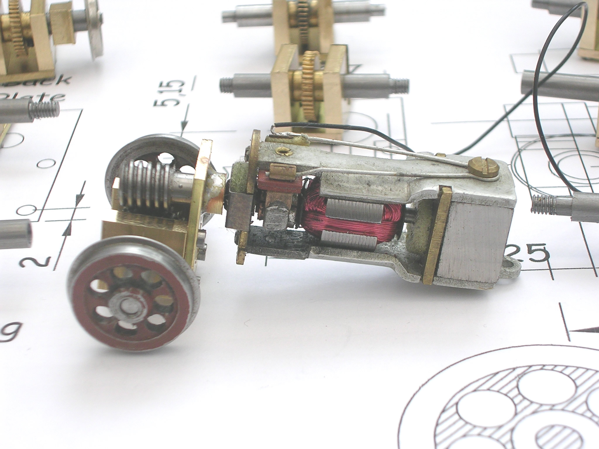 To prove that the forgoing is not all theoretical the photo shows an Airfix motor with the gearbox fitted and which is now in the first of the trams to be converted.
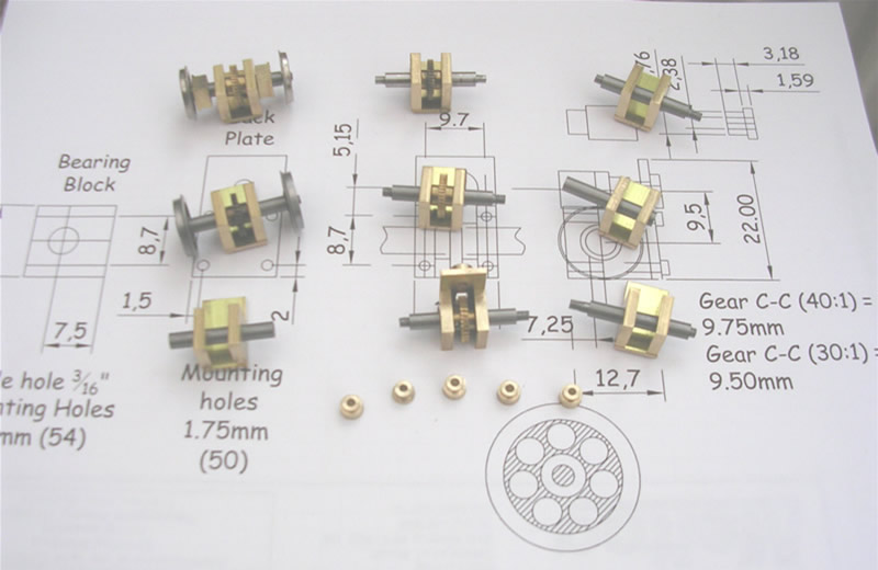 Here are a number of the gearboxes made which await allocation to the vehicles to be converted.
These do not yet have their motor shaft bearings fitted since neither motor with its shaft diameter nor the gear ratios have been determined.
While not everyone will have the need for multiple gearboxes I hope that this article has stirred some MMRS members to go on a workshop course to take advantage of the facilities there which the Society offers. If you are not yet a member, perhaps now is the time to join.