THE MODERN PERMANENT WAY (Part 2)
The copyright © for these articles is held by Colin Craig and they may not be reproduced in whole, or in part, without his express permission.
In this part the move away from the traditional wooden sleeper will be reviewed. It is a record of the early development of the concrete sleeper and covers the period up to the introduction of the Pandrol clip. As in Part 1, this is not an exhaustive summary of all the changes that have occurred, but identifies most of the major developments that have stood the test of time, and can still be seen in use today.
Once again, I am grateful for the assistance from my associates in Carillion Rail and EWS for tracking down some of the locations for photographing, and for the shots taken by my stepson in his work for Network Rail. Particular thanks also to Dr H P J Taylor of Tarmac (previously Costain and Dow-Mac), Tallington, who kindly provided the considerable background information on the development of pre-stressed concrete sleepers, dimensions, and dates of manufacture.
Unfortunately there is little photographic presentation of the third rail variants as it is outside my normal area of travel; however, the basic information is provided so that you will know what to look for. Any photos would be gratefully received. The aim is once again to demonstrate the complexity that exists, and hopefully prevent ill-informed reviews as seen in a certain model railway magazine, where the Editor criticised Peco sleepers for not having DOW-MAC on them!
THE EARLY YEARS
Prior to World War 2, some development work had been done with both steel and reinforced concrete sleepers; steel sleepers, although widely used in some parts of the world, were unsuitable for track circuiting in the absence of reliable insulation facilities; plain reinforced concrete lacked the required torsional strength.
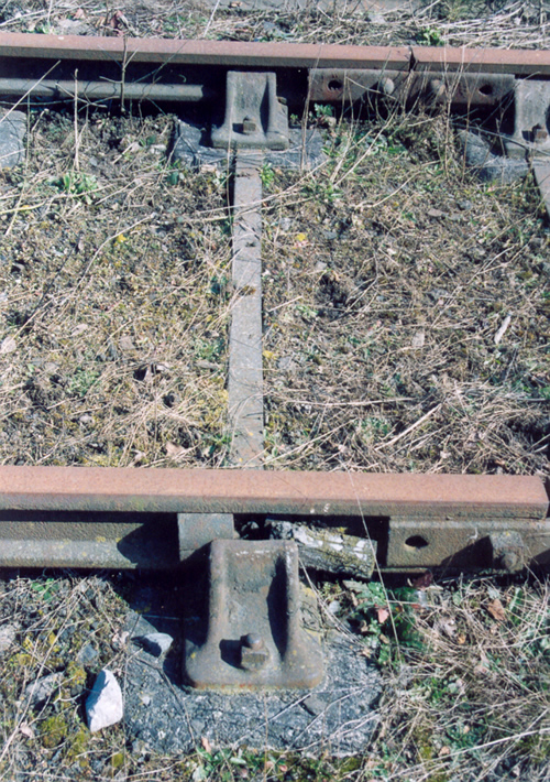
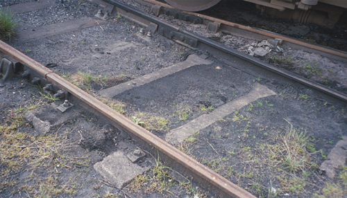
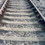
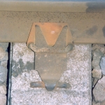
The onset of war provided the necessary impetus to find a solution, and much work was done on the development of concrete sleepers, triggered by the serious shortages of suitable timber. Several different types of plain steel reinforced concrete sleeper were used, some initiated by the private rail companies, and others by the war department; my researches are mainly based on my local ex GWR experiences, where it has been possible to see and record designs still in use today. These designs were only used in sidings and goods loops, as they were unable to withstand the stresses of main running lines, but they provided a solution to the problems prevailing at the time. The most common GWR design consisted of two cast concrete pads (referred to as pots) linked by a steel angle section tie fixed under the inner chair bolts (Photo 19). Some of the pads did not have the steel tie, presumably in the interest of materials economy. They were disliked by the P.W. Dept. but their continued survival is testament to justifying the original manufacture. This design would be particularly easy to model. The concrete pads have also been recycled, and used as building blocks for retaining walls still frequently found today. Some think this a far more suitable use!
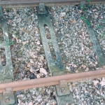
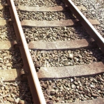
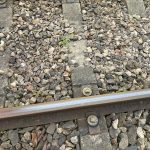
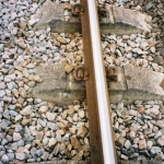
Another design is the early type of cast reinforced sleeper, again widely used on GWR sidings. These have slots in the centre to restrict the main bearing load to the areas directly under the rail; they have been seen with standard 2 bolt bullhead chairs (Photo 20) but also in War Department use with flat bottomed track bolted directly to the sleeper. As with the pots some WD sleepers were manufactured in two parts to provide the support to the rail but without the gauge control (photo 21).
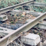

Another WD design seen is a plain reinforced design with the flat bottomed rail secured to the sleepers with offset fixings (Photo 22).
My apologies for the poor photographs, but little used, or derelict yards tend to return to nature. They have been there 60 years and are still perfectly sound.
The WD designs were used in many new sidings built at the time, but have only been seen with lightweight unidentified flat bottomed track, probably imported from North America. The other railway companies, during the war, certainly used concrete sleepers with the same constraints; an example seen in the NE has a narrowed centre with lightweight flat bottomed rail (Photo 23). Again, any further data or photographs would be gratefully received.
The solution to the problem of poor torsional strength of steel reinforced concrete was finally resolved by stressing the steel reinforcement during the casting process. The first trials with this type of sleeper were successfully implemented at Cheddington near Tring on the WCML in 1943, and followed with the construction of the Dow-Mac factory at Tallington between 1943-4, specifically for the manufacture of “pre-stressed” concrete sleepers.
E1/4
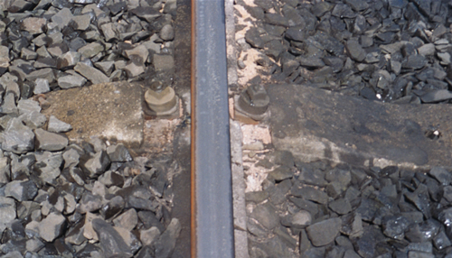
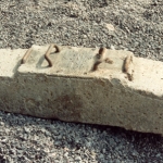
The first pre-stressed design was for use with bullhead rail with conventional 2 bolt chairs and survived in manufacture from 1944 to 1954. Dimensionally identical, there were 2 designations: E1 with through bolts for securing the chairs, and E4 for chair screws into rubber inserts in the sleeper blind holes, for track circuited areas. There is a risk that any unprotected fixing into, or through, the concrete may contact the steel reinforcement, resulting in a potential track circuit bridge. The sleepers manufactured by Dow-Mac were branded with the company name in 4.5” letters on the top surface of the concrete.
Other companies also manufactured this design under licence, but were unbranded (Photo 24). The decision to change to flat bottomed rail required the design of suitable baseplates for the E1/4 sleepers, to allow the traditional recycling; firstly there was the MRC5 for Mills clips (Photo 25), and subsequently the PAN3 & 9 for Pandrol PR clips (Photo 26).
They can still be seen widely over the network, particularly on minor lines and sidings. C&L make a superb 4mm scale E1/4, but unfortunately no suitable baseplate for flat bottomed rail.
F7, F7A, & F7B
The only other significant pre-stressed concrete sleeper design for use with baseplates was the F7 family (1957-63) for use with a special Mills clip baseplate MRC6.These are increasingly difficult to find and I apologise for the poor photos.Compared with the 11” for bullhead/MRC5/PAN3/9 these baseplate bolt centres are at 9” (Photo 27 below).
The variations are similar to the E1/4; the F7 had blind holes for rubber plugs, the F7A had beechwood plugs, and the F7B through holes for bolts.Observed with and without DOW-MAC branding. (Photo 27A below)
The second phase of development was to sleepers without baseplates, but with some form of bolt and clip fitting to secure the rail. The profiles of these types of sleeper were all very similar, but as we are now looking at current mainlines, it often becomes increasingly difficult to have sufficient exposure (modern ballasting!) to observe all of the characteristics. They all have sloping outer shoulders (except for 3rd rail versions), a 1 in 20 inclined rail seat, and a relatively deep central depression. There are pads between the sleeper and the foot of the rail, and differing forms of insulation to meet track-circuiting needs. To aid an understanding of the differences, there are 7mm scale drawings of each of the sleeper types discussed (Drawing 1) in which the section drawn is that under the centre-line of the rail seat. The key dimensional characteristics are summarised in Table 1. It will also be noted that there are often dimensionally identical designs with different suffix or prefix letters, due to the use of different steel reinforcement specifications, irrelevant to the modeller. The different branding observed by the author is also noted. The importance of this phase is its association with the introduction of CWR; the sleepers provided the required stability within the ballast, and the fixings provided the necessary creep resistance.
E10, F10, G10, and F11
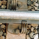
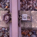
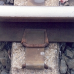
Originally manufactured between 1958 and 1963, these all used the BJB750 fixing secured with screws into beechwood-plugged holes in the sleeper (Photos 28 & 29). The F11 is a shortened version of the F10.
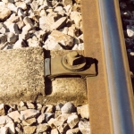
There were two post-installation developments; firstly the British Rail Research Department designed a simple replacement clip of arched spring steel, called the RD clip (Photos 30 and 30a), and, secondly, the clip/screws were replaced with Pandrol housings, secured with epoxy (Photos 31 and 32).
They can still be seen over a wide area of the network, but declining fast with the current renewals. Observed with, and without Dow-Mac branding.
Photos 30, 30a, 31, 32
F13 and F14
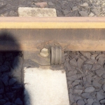
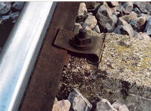
Manufactured from 1958 to 1964, these used the Dean fastening system, exclusive to the NE region. A T bolt was located in the sleeper and a collar and nut secured the rail (Photo 33). Apparently quite successful, but displaced by the Pandrol fixings for ease of maintenance. The F14 is a shortened version of the F13. Observed with Dow-Mac branding.
F16, F16A and F17
Manufactured from 1955 to 1962, these used the RN fastening clip, secured to a T bolt in the sleeper (Photo 34); also widely used on the SNCF. The F17 is a shortened version of the F16; the F16A is the third rail version of the F16, with horizontal shoulders. Observed with and without Dow-Mac branding.
EF21
Manufactured from 1962 to 1964 by Costain specifically for the WCML electrification at that time. Branded with three 1” high C’s in triangular layout. The EF prefix identifies that it is shallower with a wider base (larger footprint) specifically suitable for low ballast depths. It has a very different shape, and used the BJB625 fastening which is similar but shorter than the 750 used on the E-G10 and F11. Photographs not available. The design concept was sufficiently successful to be used for the dimensionally very similar Pandrol fitted EF25.
The third development phase was the use of pre-cast receptors for clips without any adjustment facility – “Fix and forget”, and easy to remove / replace for maintenance, such as re-padding, stressing, and rail renewal. The overall sleeper profiles remained similar to the second phase.
F19
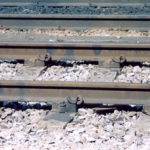
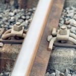
Manufactured from 1956 to 1965, these use SHC clips inserted through spring steel hoops pre-cast into the top of the sleeper (Photo 35). It is unique in having a visually raised section under the rail foot to allow the clips to be driven in (Photo 36). There are two types of SHC clip, the most common having a plain rectangular outline (Photo 37); the other has a V shaped end against the foot of the rail and is tapered at the other end (Photo 38). Note the insulators fitted under the clip, against the rail foot. Extremely widely used over the non-third-rail network. Superseded by the standardisation to Pandrol clips. Observed branded with Dow-Mac and three C’s (Costain).
CS3
This is an “oddball” from BR research, as it arrived in 1971?, well after the standardisation on Pandrol. It is not very common, but it has been included, having been found locally on the Marshes. It also has similarities to the SHC system. These sleepers were only made by Dow-Mac, and branded accordingly (Photo 39). It is unique in that the rail foot is retained at the sides by pre-cast shoulders. The clips (Photo 40) are located by cast-in hoops, and tensioned with small packing blocks. Disliked by the PW Dept, as the packing blocks are awkward to position, and rail is difficult to stress.
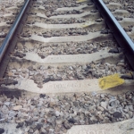
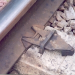

Table 2 All dimensions are in mm
| Sleeper type | Overall length | Base width under rail centre | Height at rail centre | Height at sleeper centre |
| E1, E4 | 2590 | 254 | 165 | 133 |
| F7, F7A, F7B | 2515 | 264 | 175 | 140 |
| E10, F10, G10 | 2590 | 264 | 203 | 140 |
| F11 | 2515 | 264 | 203 | 140 |
| F13 | 2590 | 264 | 203 | 140 |
| F14 | 2515 | 264 | 203 | 140 |
| F16 | 2590 | 264 | 203 | 140 |
| F16A | 2590 | 264 | 203 | 140 |
| F17 | 2515 | 264 | 203 | 140 |
| F19 | 2515 | 264 | 203 | 140 |
| EF21 | 2515 | 292 | 165 | 140 |
| CS3 | 2500 | 264 | 203 | 140 |
List of photographs (all taken by Colin Craig unless noted)
19 Pot concrete pads, Hereford yard, June 2003
20 Cast wartime sleepers, Lydney Dean Forest Railway, December 2002
21 Cast wartime sleepers WD Moreton on Lugg, November 2003
22 Cast wartime sleeper WD Moreton on Lugg, November 2003
23 by Lee Davies. Cast Wartime Sleeper with lightweight FB rail, Widdrington sidings, July 2003
24 E1 sleepers unbranded & DOW-MAC Abergavenny yard, June 2003
25 MRC5 baseplate on E1 sleeper Bath, September 2002
26 Pan9 baseplates on E4 sleepers Hereford Down relief, June 2003
27 MRC6 baseplate on F7 sleeper Perth Station, March 2000
27A MRC6 baseplate on F7 sleeper Invergordon Station, May 2008
28 BJB clip on F10 sleeper East Usk Yd, Newport, November 2003
29 F11 unbranded sleepers with BJB fixings East Usk Yd, Newport, November 2003
30 by Andrew Cole. RDclip on G10 Stokesay Castle, February 2003
31 by Andrew Cole. Pandrol conversion on F11 Church Stretton, February 2002
32 by Phil Eames. Half BJB-Pandrol conversion on F11 Coalville sidings, February 2003
33 by Lee Davies. Dean Fastening on F14 Dow-Mac sleeper, Tyne Yard, June 2003
34 by Andrew Cole. RN clip on F16 Stokesay Castle, February 2003
35 F19 CCC branded sleeper Cast-in hoops, Westerleigh, September 1999
36 F19 Dow-Mac sleepers Llantarnam, March 2003
37 SHC plain clip F19 Hereford bay platform, May 2002
38 SHC forked clip F19 Caldicot, June 2002
39 CS3 sleepers Mon Cap, September 2002
40 CS3 clip Mon Cap, September 2002
Part 3 continues with the development of concrete sleepers and Pandrol clips.