Part 2: HOW TO MAKE AN ALEX JACKSON COUPLING
At first sight it might appear a difficult task to bend the special shape of hook consistently but with the aid of two jigs this becomes much easier. The bending diagram below shows the sequence for forming the hook.
a) Using the AJ Turner Bending Jig and 180° Bending Jig
The Turner Bending Jig was designed by Graham Turner and written about in the book (Alex Jackson – The Man and the Coupling by Dave Booth, Sid Stubbs, Tony Williams et al. available from the Scalefour Society and certain booksellers). The jig has been designed to enable the user to produce couplings with consistent accuracy. To achieve this accuracy care must be taken in its assembly. For ease and speed of coupling construction it is strongly recommended that this jig is used in conjunction with the Palatine Models 180° Bending Jig.
FORMING THE COUPLING
 Cut off a piece of 11thou springy (guitar) wire about 4inches long. Use a stone to remove any burrs from the end. Push the deburred end as far as it will go into one of the holes on the side of the jig on layer 3, and bend down creating an acute angle in the wire.
 If possible try to get the wire running along the edge of the jig – it doesn’t matter if it springs back a little.
 You now need to ensure that the wire is folded back on itself completely in a really tight 180° bend.
This can be achieved with pliers, but use of the Palatine Models 180° Jig is highly recommended for this.
 Place the folded wire into the slot marked A on the jig (Photo 4). The wire must have the 5mm folded part on the top. Using the bridge to hold the wire in the slot use the prodder to push the lower part of the wire hard up along the long edge of the cut out.
 Use the prodder to ensure that a crisp bend is achieved at the start of the slot. (Photo 5).
Note: The wire will spring away from the long edge – it is meant to and this has been taken into account in the design of the jig. Do not attempt to tweak the wire after removal from the jig.
 Using the prodder bend the upper part of the wire hard up against the short edge, again making sure that a crisp bend is achieved at the slot.
 Again the wire will spring back but this has also been taken into account.
 Remove the wire from the jig and place it in the slot marked ‘B’, again with the short part uppermost.
 Using the prodder push this short part through the slot cut previously into the jig.
 Again make sure a really crisp bend is produced.
Remove the wire from the jig. Provided the jig has been made correctly, and the wire bent correctly, you should now have your first perfectly formed Alex Jackson coupling.
If you have the 180° jig you can check the angles using the angle checking portion of that jig. The coupling can now be trimmed to length and mounted using your preferred mounting method (see later).
Palatine Models also produce components to help make this easier based on the hinge/pivot plate method. See the Palatine Models website or the Alex Jackson book for more information.
 The Turner Jig before assembly. The etch also includes a dropper fitting jig.
b) As originally described
It cannot be stressed enough that perfectly accurate Alex Jackson Couplings can be made without the use of the above jigs and many people still prefer to use the method described below. However, experience has shown that the jigs produce couplings significantly faster and, more important, consistently more accurate.
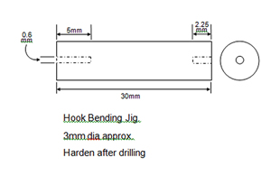 The only ‘jig’ required is a piece of metal with two accurate holes of 0.6mm dia drilled into it with one hole being 5mm deep and the other 2.25mm.
It is recommended that this is produced from an appropriate piece of rod as shown.
Next cut a piece of .011inch (0.274mm) diameter spring steel (guitar) wire about 90mm (3.5in.) long, making sure that it is quite straight and that you have stoned all burrs off the wire ends. Don’t worry that the wire comes coiled – just be careful when unravelling it. Please refer to the bending sequence shown above.
Insert one end into the 5mm deep hole of the jig and bend the wire at right angles.
Fold this bend tight upon itself using pliers or the jaws of an instrument vice.
Now insert the doubled end into the 2.25mm deep hole in the jig and bend the projecting long wire to the combined angles of 30° and 45°, bend number 3 in the bending diagram at the top of this page.
A simple template may be made to check this but with practice it can be judged quite well by eye.
With the double portion still in the jig, bend the tail to the combined angle of 60° and 60° as bend number 4. These angles do not have to be accurate to the last degree; it is sufficient to judge bends of 1/3, 1/2 and 2/3 of a right angle.
Readers are referred to Alex Jackson – The Man and the Coupling for further illustrations of construction using this method.
Flexibility
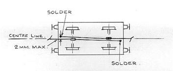
To obtain the required flexibility for positive operation within the magnetic field, the coupling wire is only 0.011inch diameter and originally needed an optimum length of 65mm (2.5inches) for effective operation, with it being anchored at the end of the wagon farthest from the hook. With this method the fact that the vehicles are really pulled from the end remote from the coupling makes it desirable to fix the end of the coupling wire as near to the centre line of the vehicle as possible in order to minimise the turning effect (see diagram below). However, with the hinged method described later the overall coupling length can be shorter and many of the potential problems associated with the fixed coupling are overcome.
The armature (or dropper)
The armature length is fairly critical. If too long, it will lock on to the magnet face and cause derailment. Worse, it may also cause distortion of the wire and lead to the need to reset the coupling; even longer and it may catch on rails at turnouts with similar quite drastic results. If too short it, may fall outside the influence of the magnetic field when uncoupling is attempted.
The length is dependent on rail height and wheel diameter and can be calculated from:
Length = (rail height+Y+10mm) – (X+0.5mm)
where X is down movement of wire before touching the axle and Y is the depth of slot sawn in the armature to aid its fitting IF using something like a small nail (see next paragraph).
So, for example, for a 12mm diameter wheel on a 2mm diameter axle to run on track made from code 75 rail which has a height of 1.9mm, – i.e. 3mm movement – armature slot depth 0.6mm: armature length = (1.9+0.6+10) – (3+0.5) = 9.00mm
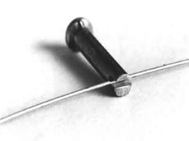
Soft Iron wire or a 1 inch (nominal 25mm) wire nail, about 0.072 inch diameter, offers suitable material to make one armature and one counterweight (the latter is used for hinged AJ’s – see below). If the nail is a large headed type then the head is removed or reduced, an accurate length is cut from the nail and a small slot sawn in one end across a diameter to receive the wire. This is the armature or dropper, and is soldered to the coupling wire at a point which will allow the armature to lie inboard of the axle by 1 or 2mm as shown below.
Experiments are currently taking place to establish the viability of using soft iron wire (available from Eileen’s Emporium) as a suitable alternative to nails. Currently 1.2mm wire is being used. 1mm dia wire is available but it should be remembered that the smaller the diameter of the wire the less there is for the magnet to attract it. It is recognised that even though 1mm soft wire was identified in the original text for the Coupling published over 40 years ago the magnets used may have been a lot stronger than the commercially available electromagnets used today, allowing a smaller diameter wire to be used (see next paragraph). Many people have used paper clips for droppers but have complained that the electromagnet has only been successful in part. If the magnet is having trouble locating the dropper it may be necessary to increase the area of the dropper ‘head’.
Please note, however, that whilst the above text is included to show how the length of the dropper may be calculated, it does not take into account the strength of the magnet used or differences in the diameter of the dropper used. It is, therefore, very strongly recommended that the above is used as a guide only and that the actual length, and/or diameter, of the dropper is found by trial fitting. Don’t get too worried by the above calculations which are provided as a guide to dropper length rather than a fixed formula.
Mounting the dropper
Whilst the dropper can be attached by eye a jig to hold it in the correct place can be made which will assist in fixing to the coupling. An etched version of this is provided on the Palatine Models AJ Turner Bending Jig. Further details of this jig can be found on Pages 40 & 41 of the Alex Jackson book.
Click here to view part 3