Page 1: Introduction and history
This coupling was developed by Alex Jackson in the early 1950’s, but it still proves difficult to be exploited commercially. However, by making the coupling yourself it is cheap and, provided you follow the design carefully, a reliable and surprisingly robust coupling.
Details of its construction appeared in the January 1960 Model Railway News, written by John Langan who used the coupling on his “Presson” layout. Those who saw it would marvel at the shunting that went on without the hand from the sky being involved in the process. It was used regularly by the Manchester EM group including Sid Stubbs, Norman Dale and Norman Whitnall. More details of its manufacture and use appeared in the Model Railway Journal numbers 55 & 56 and it is these articles that are probably more easily obtainable today.
Since the 1960’s there have been some significant developments in the operation of the coupling and modellers continue to use the idea to develop their own version of it. What is apparent is that the design that Alex developed all those years ago is still a great way of providing hands free coupling and uncoupling of stock.
Who was Alex Jackson?
The late 1940s and early 1950s was a period when many developments were taking place in the hobby following its revival after WWII. At that time, Alex Jackson gave much encouragement to many fellow modellers by his brilliant approach to the problems of mechanisms, good running, trackwork, and true scale modelling. He first worked in a scale of 3/8″ to 1 foot (1:32) and his garden railway, running off 100 volts AC supply, was a source of enjoyment to all who visited him. Stories exist of his unfortunate cat which never seemed to learn to keep off the track when a running session was in progress – with surprising results!
A fine example of one of his locomotives in 3/8in scale may be seen in the March 1948 Model Railway News. Later, Alex changed to 4mm scale EM gauge, 2 rail using split axles, metal wheels and insulated frames for locomotives. He saw the advantage of using the higher than usual voltage of 24V DC which was quite revolutionary at that time. This, of course, meant the need for home built motors which he used with flywheels to obtain smooth and controllable running which can still be compared with the best of today. No gimmicks in the controls either, just a plain resistance wire controller. His attitude to modelling and an example of his construction methods may be seen in the description of his 4mm scale LNWR 0-6-2 side tank locomotive in the MRN for June 1950. The photograph clearly shows the early version of his coupling. Alex died in October 1952 after an operation, when he was in his early thirties, and the hobby lost not only a most distinguished exponent but an enthusiastic leader who by his example helped to raise the standard of modelling to a level which we still appreciate today. The Alex Jackson or AJ coupling is a fine memorial to this pioneering modeller.
The coupling
Alex first demonstrated the coupling at a meeting of the Manchester Model Railway Society in February 1949. The Society continues to receive enquiries for information about it and, although the coupling in its basic form has changed very little since its conception, a revised description which includes further information on the latest jigs to aid its construction is now presented. The Society believes that nothing can beat the visual appearance of screw and 3 link couplings but, if hands-free coupling and uncoupling are required, then the Alex Jackson Coupling is the most unobtrusive and versatile automatic coupling available. It has been in use in one form or another for over 60 years, but it must be emphasised that whilst it is capable of satisfactory operation in the hands of careful modellers it is not suitable for very rough handling, and accurate maintenance of all angles and dimensions is essential for faultless operation.
By accurate setting in the first instance and maintaining this setting from time to time, the coupling will operate faultlessly and indefinitely. Its main advantages are:
- It is unobtrusive.
- It is quiet in operation.
- It is reliable if properly made.
- It is cheap.
- Couplings are identical at each end of the vehicle, so that turning end to end does not affect performance.
- No mutilation of wagon headstocks or attachment to buffers is necessary.
- The pull for uncoupling, being downwards, ensures that the vehicle stays on the track.
- The electromagnet may be energised by a push button on the control panel before a wagon reaches it with the certainty that it will uncouple as the wagon passes through the magnetic field.
- Uncoupling while moving, with the loco pushing and buffers under compression with couplings slack, is positive and the magnet will operate only one coupling at a time.
- Only one uncoupler is required per fan of sidings.
- After being uncoupled at the magnet location, vehicles may be parted and left at any position on the layout. This allows realistic shunting to take place.
(NB: Some of the advantages listed above are superseded by DCC operation of the coupling, which gives even greater flexibility of operation – this is discussed briefly later on.)
The hook
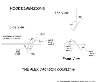 The ingenuity of the coupling lies in the design of the hook.
Modellers may be put off making and using the couplings, but the jigs produced by Palatine Models and described later do ensure that correctly made couplings are produced.
Each feature is important and plays a part in the action of coupling and uncoupling. The method used for forming the hook, as devised by Norman Whitnall, requires the wire to be bent back along the top of the nose with the tail coming down on the right side of the shank when the coupling is viewed end on. This ‘handing’ is important so that wagons will couple with each other. This way of bending the hook shape produces a strong hook which tightens upon itself when under load and is capable of handling long trains. The hook does not require to be soldered but this may aid longevity and reduce maintenance.
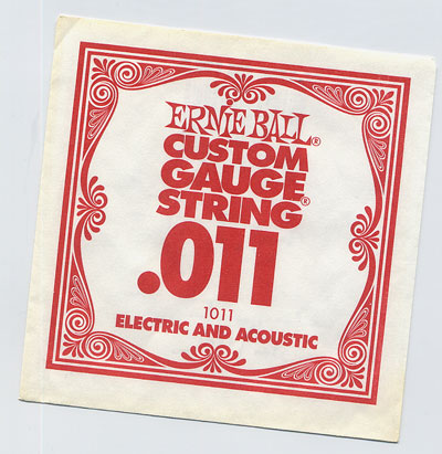 The material used to form the hook is 0.011inch diameter spring steel wire (32 SWG or 0.274mm).
This is easily available from a music shop in the form of guitar strings and the picture shows a common variety.
Attaching the hook
As originally conceived by Alex Jackson each coupling was fastened at the centre of the wagon or bogie and uncoupling was by mechanically pushing one coupling upwards. The change to pulling down rather than lifting up to uncouple was made in order to overcome problems of lifting the vehicle as well as the coupling. The change to fasten at the far end of the wagon was made in order to gain greater flexibility of the wire for magnetic uncoupling, without decreasing the wire diameter.
While the version as described works with complete satisfaction and has done so for many years on a number of layouts, some features have been capable of improvement.
The coupling wire with an unsupported length of some 65mm (2.5 inches) is vulnerable when stock is continually having to be packed and unpacked for exhibition work; also, the fact that four wheel vehicles are pulled from the opposite end to the coupling hook may cause difficulties on sharp curves with heavy trains, or if a particular item of goods stock is noticeably lighter than the rest. Also, the adjustment of the shank to achieve 10mm above rail requires a fair amount of skill and practice which not all modellers seem able to develop. The design of the coupling means that it must be purpose built for each vehicle and fitting is not always easily adjustable to meet all the critical dimensions.
Radical re-thinking
A method of anchoring the coupling on the transverse and longitudinal centre lines of the vehicle, or as near as possible to it, was first achieved by Norman Whitnall, a close friend of Alex Jackson, by hinging the wire at that point. Early attempts to improve wire flexibility had the wire hinged at the centre and then extended to the end remote from the hook, such that this end flexed upwards when the hook was pulled down. This was not totally successful but led to the idea of fitting a counterweight to this remote end, so that the weight was raised as the hook was drawn down. This worked satisfactorily and led to the further refinement of mounting the hinge on an adjustable plate, making it easy to locate the hook tail relative to the buffer faces. Mounting the coupling on an adjustable hinge plate also means that the wire itself does not need to be ‘tweaked’ if the coupling goes out of alignment, unlike with the fixed version. Experience has shown that too many adjustments to the wire weakens the metal causing it to fracture.
A height bar is an integral part of this design as the counterweight holds the shank of the coupling against the height bar and adjustment for coupling height is always by adjustment of the height bar rather than by the wire. The shorter free length of wire makes the coupling more robust without losing the delicacy of action. An early error was the attempt to try to achieve a point of balance between the armature and the counterweight in the belief that this was required for correct action. In fact the counterweight has two purposes; to hold the couplings shank against the height bar and to supply a source of inertia to the coupling when in the act of coupling or uncoupling. Without sufficient inertia both couplings tend to dip when coming into contact at coupling; similarly, when a coupling is drawn down by the magnet for uncoupling, its fellow coupling must have sufficient inertia to remain in the normal position. The counterweight must therefore be relatively heavy compared to the armature at the other side of the hinge.
Detailed design
Having established the method as a sound working proposition, it was thought necessary to devise a fairly standard type of fitting for vehicles, with the intention that, where possible, parts could be produced in bulk from standard materials. That said, there is nothing final about these designed parts and they may be freely adapted as long as there is no departure from the principles. As an example, the base plate described later for use with four-wheel wagons will not always fit wagons with fully modelled underframes but it should be possible to mount a hinge plate directly on the underframing, if desired.
The following text shows how to make and fit both the fixed and hinged version of the coupling using commercially available jigs and components. In considering the use of these jigs and components the reader should be aware that:
- the coupling itself needs to be made by hand
- jigs are not required to make perfectly satisfactory couplings – they just make the process so much easier and quicker
- some of the jigs can be used to make both the fixed or hinged type of coupling but clearly the hinge plates and fold up base plates are for the hinged coupling only.
How we got to where we are today
In 1990 Norman Whitnall was invited to demonstrate the Alex Jackson Coupling at Scalefour North. Although Norman was still an active modeller, he realised that others needed to be trained in the vagaries of the Alex Jackson Coupling and invited MMRS members Tony Williams and Andy Goodman to be trained up. Tony accompanied Norman to Scalefour North and was able to listen to many questions and answers about the coupling throughout the weekend.
In 1997 when an invitation to demonstrate the Alex Jackson coupling at Scaleforum was received, Norman decided that the trip was too far for him and so Tony went on his own. Nobody could have predicted the level of interest in the coupling over that weekend but a similar invitation was received the following year, and the one after that, and ….. !
Tony was, of course, demonstrating how to make the coupling using the methodology taught to him by Norman Whitnall. However, working under the lights for several hours at Scaleforum got him thinking that there must be easier ways of producing the coupling. Graham Turner from the Scalefour Society’s Glevum Area Group had already shown him an ingenious jig he had produced to form the coupling and, with colleague Morgan Gilbert, had produced a jig to hold the coupling head when attaching the fixed coupling to a wagon. Text for the book, ‘Alex Jackson – The Man and the Coupling’ was progressing and another visit to Scaleforum was imminent. It was whilst rushing to fit some hinged couplings to stock in time for the show that identified one of the problem areas. How do you hold the coupling in the correct plane and make the right angle bend in a similar plane for the coupling to fit the hinge?
At Scaleforum that year that another difficulty was overcome. The first bend in the production of the coupling requires the wire to be bent over to a tight 180°. This can be a bit fiddly so a jig to make the bend was devised and the idea for a further jig to make a right angle bend whilst holding the coupling correctly was discussed with fellow MMRS member Ralph Robertson. Ralph had experience of the etching process and put his expertise into devising kits to produce both jigs commercially. He also put his mind to devising a way to reproduce Graham Turner’s jig. All these and some other useful jigs devised by Graham are available through Palatine Models or from the Scalefour Society stores (members only). We are indebted to Graham for sharing his experiences with us. Regrettably, the availability of some of these jigs and fittings came too late to be included in the Alex Jackson book with a level of detail that befitted them but it does prove that the development of the Alex Jackson Coupling is far from over.
The development of these jigs may lead the reader to think that what follows is about the latest developments on the coupling only. Far from it, as the original description about forming the hook is just as relevant today as it ever was. The only difference now is that a series of jigs has been produced which simplifies its construction and fitting and allows the coupling to be made correctly on a much more consistent basis. For this reason both descriptions are included on page 2.