Part 4: Coupling and uncoupling
Coupling
The action of coupling may be followed by reference to the drawing below in which wagon ‘B’ approaches wagon ‘A’ and the noses of the couplings slide against each other. Further movement of ‘B’ leads to contact of the tails of the couplings and a gradual sliding movement in the horizontal plane takes place until the tails pass each other. The wires then spring back to the central position with the shanks in line. The coupling hooks are now in the correct relationship for engagement and at this point the buffers should make contact. Upon reversing the motion of ‘B’, the tails of the couplings slide along the shanks and engage, whereupon wagon ‘A’ is also drawn along with wagon ‘B’.
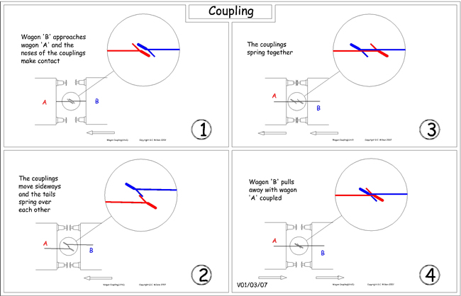
It is important that the couplings spring together before the buffers make contact, and to ensure this, the end of the hook tail should be 0.25mm (0.010in.) from the buffer face as shown in the drawings. There should not, however, be excessive clearance, otherwise when the locomotive is pulling a train the gaps between the vehicles will be unrealistic. Note that it may be necessary to add weight to a free running vehicle of light construction, otherwise wagon ‘A’ might simply be pushed along by the friction of the coupling tails.
From the foregoing it will have been seen that two wagons may be coupled simply by bringing them together and that the magnetic field plays no part in the operation. Coupling may therefore take place anywhere on the layout, except on sharp curves. (a problem which will be discussed later). It will be realised that for two vehicles to come together and the coupling hooks to engage correctly (i.e. centrally), sideplay of the vehicle on the track must be small. The wheel and track relationship of P4, EM, or OO finescale (but not necessarily proprietary) is satisfactory; however, sideplay of axles in their bearings must be held to a minimum. Greater offset than 1mm from centre line may cause the tails or noses of the hook to pass without making contact.
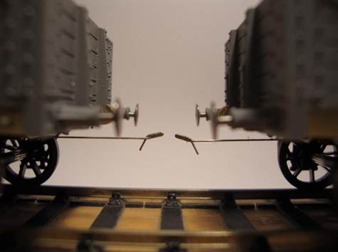 Wagons approach each other with the couplings lined up.
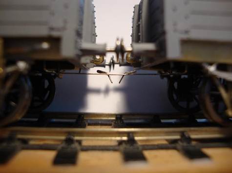 Coupling tails slide over each other and the buffers touch.
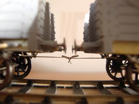 The train pulls away and the coupling tails engage.
Uncoupling
Referring to the drawing it can be seen that wagon ‘B’ is pushing wagon ‘A” by contact of the buffers and the couplings are therefore slackened off. Vertical movement of either coupling will disengage the hook, and in the electro-magnetic system we arrange for one coupling to be pulled downwards by arranging an electro-magnet between the rails. After having passed through the magnetic field, the coupling springs back upwards but now the tail is on the opposite side of the shank. Upon reversing the direction of motion of wagon ‘B’ the tails slide past the noses of the hooks and wagon ‘A’ is released. It will be found that one gets a less jerky action if the coupling of wagon ‘B’ is pulled down to release wagon ‘A’. Note that the path of coupling ‘B’ is downwards with a slight horizontal movement and that of coupling ‘A’ mainly horizontal.
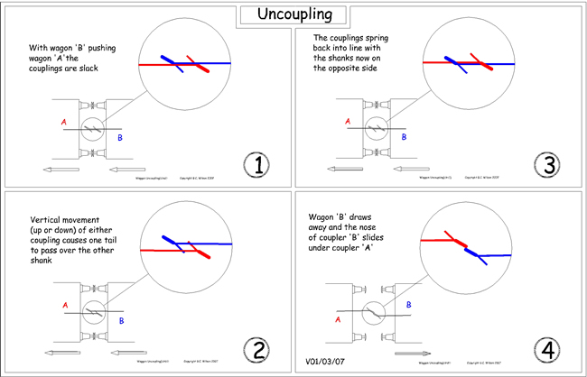
After uncoupling in the magnetic field, the wagons may then be pushed along until a desired location is reached, at which they may be parted without further ado. Uncoupling and parting of vehicles are therefore separate and distinct operations which take place at quite different locations. This means that one electromagnet positioned at the start of a number of sidings is all that is required to split a whole train. Herein lies the ingenuity of the original design, which distinguishes it from most other types of coupling. By leaving the magnet energised, the whole train would of course become uncoupled as it passed over the magnet position. If wagon ‘A’ is of light construction and free running it can happen that as wagon ‘B’ draws away from it, having been uncoupled, the friction of disengaging may draw wagon ‘A’ along. In this case some weight needs to be added to it.
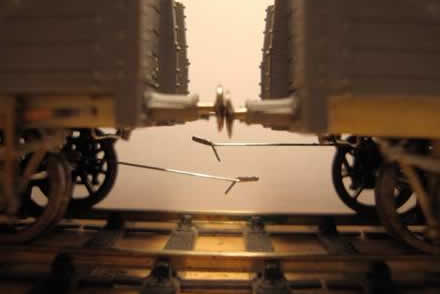 When the wagons are propelled the couplings slacken off.
The magnet is energised, pulling one coupling downwards.
 Current to the magnet is stopped and the coupling springs back leaving the tails disengaged.
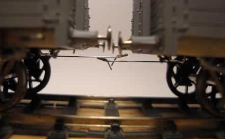
When one wagon is moved the head of one coupling simply slides over the other one.
The Electromagnet
To uncouple it is necessary for one coupling to be pulled down vertically. Wagon ‘B’ is moving over the electromagnet whilst pushing wagon ‘A’. By pressing a push button switch on the control panel the coil is energised and a magnetic field is created between the rails. The dropper (or armature) attached to the shank of the coupling is attracted to the magnet so creating the vertical movement downwards towards the wheel axle. In this lowered position sufficient movement has been made to disengage the hook, but the dropper must not touch the magnet face. If it does, the locomotive propelling the stock will not be able to move the vehicle, as mentioned above, which may result in a large pile-up!
The position of the electromagnet on the layout should be indicated by some unobtrusive marker, especially if it is some distance away from the controller. The operator is then better able to see the relationship between the moving wagons and the magnet. If there is a location where all vehicles are required to be uncoupled, a permanent magnet of suitable size and power may be fitted instead of an electromagnet.
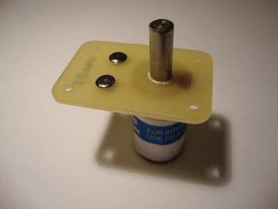
PK Models electromagnets were used on the test track in question. More recently a similar magnet sold by Model Signal Engineering has been used.
No doubt other magnets are equally as good but the idea of this article is not to review every magnet currently on the market. These magnets may also be incorporated into a DCC supply – as with anything electrical, if you’re unsure about how to do this please stick to the recommended power supply.
Uncoupling remotely using DCC
This has been developed by Nigel Cliffe and allows stock to be uncoupled anywhere on a layout without the need for any ‘delayed action’. The design works by rotating the head of the coupling rather than by moving it downwards thus uncoupling can be undertaken anywhere on the layout on demand since the locomotive is under DCC control. This is particularly useful at, for example, a branch line terminus where the locomotive has to run round. When using an electromagnet the train has to be stopped in exactly the correct location for uncoupling to take place. With DCC such problems are eradicated completely. The system is fully compatible with stock using non DCC AJ Couplings.
A more complete explanation of this system, including photographs, is contained on pages 54 and 55 of ‘Alex Jackson – The Man and the Coupling’.