MODERN PERMANENT WAY (Part 1)
The copyright © for these articles is held by Colin Craig and they may not be reproduced in whole, or in part, without his express permission.
To most Modern Image modellers there are two basic considerations for trackwork:
- The use of flat-bottomed track
- The use of concrete sleepers
Unfortunately, as with most things in the real world, the situation is far more complex. There has been very little put down in writing for modelling reference, and materials available are equally sparse for finescale reproductions. This is the first of a series of articles to improve basic knowledge of some of the many changes that have taken place in the last 50 years, which in turn will allow modellers to produce layouts of improved fidelity. It will not be possible to cover all the changes which have occurred over this period, but the focus will be on those which have been observed and recorded by the author with considerable assistance from many colleagues working on the railway. It is hoped that this will allow an opportunity to view the real permanent way in a new light, and to understand the enormous variety that exists out there.
The railway companies have always been very good at recycling part expired materials, often by use in lower traffic volume, or speed, areas and this provides much of the variety and the opportunity to observe it. Equally, renewals occur over relatively long periods, and it is almost the exception to find the same track specification on the up and down lines of many main lines. For example, within the station limits of the Abergavenny signal box, there are five different types of CWR (Continuously Welded Rail) track sleepers, three designs of adjustment slip, two different types of jointed plain track, three different turnout constructions (we call them points) and three turnout operating systems; all this within less than a mile and a half of railway!
RAIL PROFILES
From the early days, bullhead rail was the standard on railways in Britain, whilst elsewhere in the world, flat bottomed rail was generally used. Bullhead rails are mounted on chairs, with the rail inclined inwards at an angle of 1 in 20, so that the rail head has a profile matching the coning of the wheel tyre. Flat bottomed rail was generally mounted directly on the face of the sleepers, and secured with simple rail spikes; it was quicker and cheaper to install, but less sophisticated.
In the 1930’s, with increasing loads, and vehicle speeds, the “Big Four” railway companies, with the exception of the Southern Railway, started performing trials with flat bottomed rail. There was a general acceptance that the existing track was no longer adequate, without increasing the maintenance costs. The extra rigidity and strength of flat bottomed rail, and the opportunities for improved, lower maintenance, fixing systems (baseplates instead of chairs), could no longer be ignored; unfortunately, this work was curtailed by the outbreak of war in 1939.
Following nationalisation of the British railway system in 1948, it was decided to standardise on two totally new profiles for flat bottomed rail; BS11-98 for light duties (branch lines and sidings) and BS11-109 for main lines. In these British Standards’ designations, BS11 refers to the British Standards Number, and the subsequent digits to the weight of the rail in pounds (lbs) per yard.
By 1959 it was decided to replace the 109lb/yd rail with BS11-110A (110lb/yd) with the letter A indicating that the sides of the rail head are inclined outwards at an angle of 1 in 20. This closely matched European UIC54 (Union Internationale des Chemins de Fer 54 Kg/metre). However this was subsequently changed again in 1968 to BS11-113A (113lb/yd) after a serious accident at Milton near Didcot which was attributed to a weakness in the central web.
There is a further change, at present in its infancy, to increase the strength of the rail further, by adopting European UIC60 (60Kg/metre) which has been used on their major routes for some years. As this will require totally new specifications, particularly with S&C, it is not intended to cover any further elements of this rail profile in these articles.
Comparative dimensional and weight data of the different rail sections is shown in Table 1.
All dimensions are in mm but the weights are shown in both metric and imperial units.
Table 1
| Origin | Weight lb/yd | Weight Kg/m | Height H mm | Foot F mm | Head W mm |
| LNER, LMSR, GWR | 110 | 54.7 | 158.75 | 152.40 | 73.03 |
| 113 | 56.4 | 168.26 | 139.70 | 69.85 | |
| British Railways / Railtrack | 98 | 48.9 | 142.88 | 139.70 | 69.85 |
| 109 | 54.4 | 158.75 | 139.70 | 69.85 | |
| 110 (A) | 54.7 | 158.75 | 139.70 | 69.85 | |
| 113 (A) | 56.4 | 158.75 | 139.70 | 69.85 | |
| Railtrack / Network Rail | 121 (A) | 60.2 | 172.0 | 150.0 | 72.0 |
BASEPLATES ON WOODEN SLEEPERS
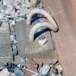
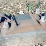
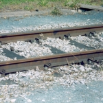
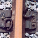
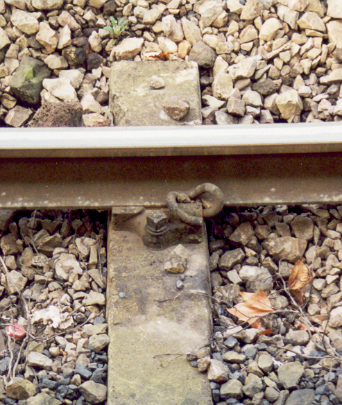
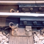
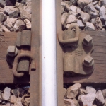
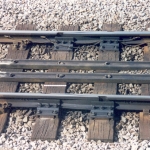
At the time of the introduction of flat bottomed rail as a new standard, all plain track was jointed with a standard panel length of 60ft, and simple elastic spikes on inclined baseplates were used; the spikes secured the rail to the baseplate, and the baseplate to the sleeper. The two most common baseplates were the BR1 which had a single spike on the outside and two spikes on the inside (Photos 1 & 2) and the BR2 which had a “hooped” Macbeth spike on each side (Photos 3 & 4).
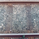
These are still relatively easy to find, especially off the main lines. Many hundreds of miles of track were laid with these fittings between 1948 and the late 1950’s, so are equally applicable to the late steam as well as the diesel and electric era.

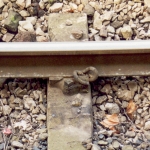
The BR3 was common on the third rail electrified lines to overcome the difficulties associated with handling spikes adjacent to the live rail. This design had a lip to hold the outer edge of the running rail, with a single baseplate screw to secure the outer side of the baseplate to the sleeper. The inside of the rail and baseplate were secured with two elastic spikes as on the BR1 (Photo 5).
The BR4 and BR5 baseplates were later developments to try to solve the problem of low creep resistance with this type of fitting, but were eclipsed by the need to have more sophisticated fittings for CWR. Whilst I have drawings of these designs, any photographs would be welcomed; the most likely locations are sidings/yards.
The introduction of CWR in the 1950’s placed new requirements on rail baseplates, and this form of track became the standard on all main lines by the mid 1960’s; also the increasing use of concrete sleepers without the need for baseplates was gathering momentum. This will be covered in some detail in the next section.
For use with wooden sleepered CWR, baseplates and fittings fall into two types; the same principles apply to concrete sleepers:
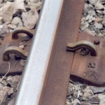
1. Those with a threaded assembly securing a form of spring clip against rail foot – the threaded element allowing adjustment of the tension. An example is the ST baseplate with 4 bolt fixings to the sleeper, and T bolts securing the clips against the rail. Examples with a saddle clip and a KT clip are shown in Photos 6 & 7. This system is most commonly used on early S & C rather than plain track. Its main disadvantage is the need to check and maintain the tightness of the fixings.
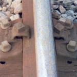
2. Those with a fixed receiver for a spring clip with no facilities for adjusting the tension against the rail. Examples of this type are the Mills (mid 1950’s to mid 1960’s) and Pandrol PR clips (mid 1960’s onwards). The Mills clip uses a 4 bolt baseplate with an outline similar to the ST; it is also used on S & C, but more commonly on plain track (Photos 8 & 9).
The Mills clip is prone to corrosion in the lower part within the baseplate and with loss of tension against the rail foot.
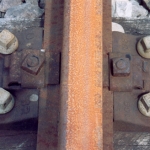
There are several different types of Pandrol baseplate, but, for modelling purposes, those most frequently used can be grouped into three main types:
Pan1, 2, 6, & 11 with 3 securing bolts/4 Pandrol clip housings (Photos 10 & 11)
Pan8 with 3 lockspike fixings/4 Pandrol clip housings (Photos 12 &13).

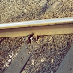
Pan3 & 9 with 2 securing bolts/2 Pandrol clip housings suitable for lower category lines on wood but more commonly on recycled early concrete sleepers (Photo 14).
Many Pandrol baseplates have the facility for 4 clips, but, with the exception of the fabricated crossing nose, only 2 clips are required. Right hand Pandrol PR clips are used as standard so that the 2 clips are diagonally opposed on a baseplate.
Left hand Pandrol PR clips are used if access from the right is not possible (Photo 15) or if one of the housings is damaged. The Pandrol clip system became the BR standard in the mid 1960’s, with all other fixings being made obsolete. Later designs of Pandrol clip – the “e” clip, and “fast” clip, are not used on baseplated track, however the former uses the same housing as the PR clip and it is not uncommon to see them incorrectly used on baseplates (Photo 16).
The dimensions of wooden sleepers have not changed during the period covered by this review and remain at 10” x 5” x 8’ 6” although now specified in metric units. Note that this is not an exhaustive list of all the fittings that have been used; the focus has been on those that were used in quantity and have passed the test of time.
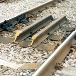
One other feature of CWR is the requirement for adjustment switches. These are located between CWR and S&C where the latter is not specifically built to withstand the stressing forces, and also between CWR and structures subject to significant expansion such as long bridges. They are sometimes, erroneously, referred to as breather switches. Few people realise that CWR is just that, and can be several miles without an adjustment slip. In simple terms, the rails are pre-tensioned (called stressing), so that in cold weather they are under tension, whilst in hot weather they are under pressure. To achieve stability, ballast specifications have changed that have significant visual differences, important to the modeller; these will be discussed in a later article.
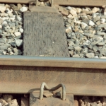
Adjustment switches are normally mounted on 12” x 8’ 6” S&C timbers, but the very latest constructions use concrete bearers. There are special baseplates for the sliding joint and the four timbers or concrete bearers are linked with two lengths of either bullhead rail bolted flat, or flat bottomed rail bolted upright (Photos 17 & 18).
The finescale reproduction, in 4mm, is potentially problematic. The clips that secure the foot of the rail to the baseplates are relatively small; for example, a Pandrol PR clip is made of 0.75” diameter steel rod. The 4mm equivalent is 0.25mm; quite delicate in brass, let alone plastic. The well established practices of using rivetted ply, or PCB sleepers can provide the necessary strength, leaving the fastenings to be represented cosmetically. This is a challenge waiting to be taken up. (The author is generating some Pandrol masters, as well as etchings to create the BR1 and BR2 fittings).
List of photographs (all taken by Colin Craig)
- BR1 baseplate track, Gloucester 1999
- BR1 baseplate, Hereford 2003
- BR2 baseplate track, Gloucester 1999
- BR2 Macbeth spike, Hereford 2003
- BR3 baseplate track, Bournemouth 2003
- ST baseplate – saddle clip, Abergavenny 2003
- ST baseplate – KT clip with top saddle, Pontrilas 2003
- MRC baseplate – Mills clip track, Hereford 2003
- MRC baseplate – Mills clip, Hereford 2003
- PAN6 baseplate – Pandrol PR clips Track, Hereford 2003
- PAN6 baseplate – Pandrol PR clips, Abergavenny 2003
- PAN8 baseplate – Pandrol PR clips track, Eastleigh 1997
- PAN8 baseplate – Pandrol PR clips, Pontrilas 2003
- PAN9 baseplate, Ponthir 2004
- S&C with left hand Pandrol PR clip, Abergavenny 2003
- PAN11 baseplate with incorrect Pandrol e clips, Abergavenny 2003
- Adjustment switch – bullhead rail bracing, Abergavenny 2003
- Adjustment switch – FB rail bracing, Pontrilas 2002