Part 3: How to fit a coupling
a) Using the Hinged Method
The hinged version of the coupling offers several advantages over the original fixed version.
- it is adjustable in all directions without having to physically tweak the wire which, over time, may cause it to break
- it is more positive in operation
- it doesn’t require any form of centre control
- it is more robust
These benefits mean that there is much less maintenance required, but if needed, it is much easier to undertake.
To fit AJ couplings using the hinged method we will use the example of a 9ft wheelbase wagon. Requirements for such a vehicle will be 2 couplings, 2 pivot plates, and 1 baseplate. Etched pivot and baseplates have been produced by Palatine Models or they can be ordered through organisations such as The Scalefour Society.
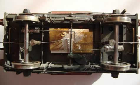
Basically a coupling needs to be bent so it is able to be threaded through a pivot plate with the coupling ‘tail’ bent towards the end of the wagon furthest from the coupling head. This pivot plate is then attached to the baseplate which has been fixed to the underfloor of the vehicle, preferably in a centrally located position. Using a different pivot plate a second coupling is threaded through and this is then attached to the same baseplate as the first. To operate each wire will require a dropper to be attached, placed immediately behind the axle nearest the coupling head. At the other end a counter balance will need to be added (usually but not necessarily out of the same material as the dropper). This is all perhaps best explained by the photographs below.
However, it should be noted that without the use of a jig it can be quite difficult to bend the wire in the correct plane to thread through the pivot plate whilst maintaining the coupling head at the correct angle. If bent incorrectly the coupling is completely ruined. A pivot bending jig has been produced which overcomes this problem and enables the correct bend to be made every time.
Instructions on using this jig are included in the kit and are available on the Palatine Models website.
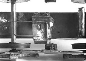
Essential to the operation of an AJ coupling will be a height bar, being a simple stirrup of suitable wire (0.4mm approx) fastened transversely across the underside of the vehicle and of such size that when the coupling shank springs back up to it after being activated by the magnet the required coupling height of 10mm above rail level is obtained. DO NOT, UNDER ANY CIRCUMSTANCES, USE THE LOWER EDGE OF THE BUFFER BEAM FOR THIS PURPOSE. The lower edge of buffer beams on rolling stock can be at different levels and will, therefore, create inconsistency in the operation of the coupling.
Counterweight
If using a nail for the dropper the remainder, with the point removed, will provide a piece about 12mm long which is soldered at the far end of the coupling wire at a point which will allow it to lie inboard of a wheel and above the axle (see photo). For normal four wheel wagons, the mass of this portion of nail, fitted as described, is usually sufficient to balance the dropper and to provide sufficient inertia to overcome the friction force of the coupling tails when coupling or uncoupling.
If using another material, such as soft iron wire, an appropriate length will need to be cut which will allow the coupling to function properly. Please note that this will need to be of greater mass than the dropper (see below).
It is possible for the counterweight to be too light, or to be fitted too close to the hinge. In such cases it will not overcome the weight of the armature (dropper) and maintain the hook at the correct height, by not providing sufficient inertia to overcome the friction forces of the coupling tails. This will cause problems when coupling or uncoupling. However, it is also possible for the counterweight to be too heavy or fitted too far away from the hinge, causing upward forces at the armature which are too large to be overcome by the downward forces set up by the uncoupling magnet. Experience achieved by a little trial and error will soon find the correct weight/position!
Scratch building the hinged version
Please note the following section is taken from the original website version of the coupling and also appears in The Alex Jackson Book. It is included here for completeness to enable those who do not wish to purchase the Palatine etched versions to make their own.
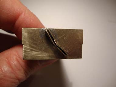
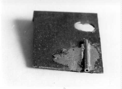
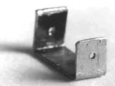
The hinge
Two types of hinge have been used. The first one utilises a short length of 23 gauge hypodermic needle as a tube through which the coupling wire is threaded so as to provide a pivot point. The needle or bracket is soldered to a small brass plate which has a 12BA slot and one edge turned at right angles away from the pivot. The second uses two holes of 0.3mm (0.012inch) diameter in a small bracket bent in such a way as to provide a similar pivot point to the hypodermic needle
 |
 |
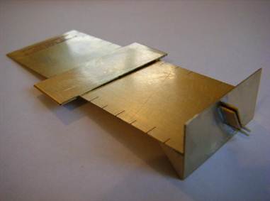
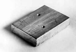
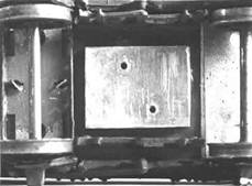
Mounting
The hinge plate is mounted on a base plate made from standard section aluminium 1/2 inch by 1/8 inch. A length of 3/4 inch will fix nicely to the bottom of a typical four-wheel wagon and with two 12BA tapped holes will accept the hinge plates of both couplings, one 12BA screw per coupling being quite adequate to secure the hinge plate with the folded lip maintaining alignment against the base plate edge. The longitudinal slot in the hinge plate allows adjustment of the tail to buffer face dimension (0.25mm or 0.01 inch).
For bogie vehicles, 6 wheel vehicles and other non-standard vehicles, then single coupling base plates can be made to suit the mounting conditions or, in some rare cases, it may be necessary to produce a non-standard hinge plate or even to make the hinge a fixed part of the vehicle. Such an arrangement causes loss of the ready adjustment of tail-to-buffer face dimension referred to earlier but the hinged version of the coupling is more readily adapted to unusual vehicles than is the ‘flexy’ version
  |
|
|
For bogie vehicles, 6 wheel vehicles and other less than standard vehicles, then single coupling base plates can be made to suit the mounting conditions or, in some rare cases, it may be necessary to produce a non-standard hinge plate or even to fix the coupling to part of the vehicle. Such an arrangement causes loss of the ready adjustment of tail-to-buffer face dimension referred to earlier but the hinged version of the coupling is more readily adapted to unusual vehicles than is the ‘fixed’ version.
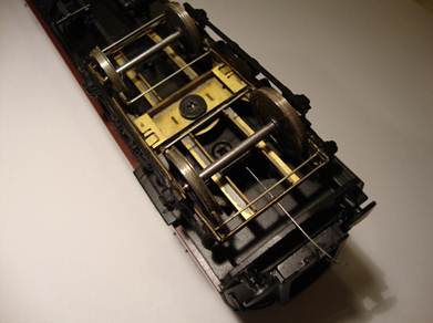
 This shows how the hinged version has been adapted to fit a coach bogie.
b) Using the original fixed version
In essence fixing the coupling to a vehicle is very simple. All that is required is for it to be held with its nose in exactly the right position in relation to the buffer faces and vehicle centre line. The nose and tail of the coupling must also present the correct angles. With this achieved the far end of the wire is then attached to the vehicle as close to the centreline as possible but at a point where none of its length will interfere with the movement of the coupling at the opposite end of the vehicle (see diagram in Flexibility above).
Whilst stating that this is very simple, in practice it can be anything but … however, help is at hand. There is a jig available designed by Graham Turner and available from the Scalefour Society which attaches to the buffers of the vehicle and holds the coupling at the correct distance from the buffer heads with the nose and tail at exactly the right angle (see below).
Two other items will be essential when fitting this coupling
- A height bar referred to above
- Some form of centring guide to ensure the coupling returns to its central resting place. This may be a piece of plastikard with a ‘v’ cut in to it or two short pieces of wire fixed together under the wagon and then opened out to form a ‘v’. This is not required if using the hinged coupling as the length of coupling projecting from its fixing point, i.e. the hinge, is much shorter than it is with the fixed coupling.
Fitting couplings to coaches
The first question is whether to fix couplings to the coach bodies or the bogies. Mounting AJ’s on coach bodies comes down in part to the over-hang of a coach body in relation to the bogie on curves, the radius of curves and the nature of overhang on other vehicles. Such parameters typically affect standard OO couplings as well and makes mounting AJ’s on bogies rather than coach bodies almost essential, even if the overhang is identical on all stock. In general coach body mounted couplings would only be feasible if stock was to be operated on track with prototype radius curves (plain track and turnouts) only, which may cause compatibility issues if stock is to be used elsewhere.
Fixed AJ’s can be attached to most coach bogies as coaching stock rarely has to be uncoupled. If a locomotive has to detach itself from a train to, say, run round at a terminus, then the uncoupling can be done from the locomotive as only one coupling needs to move when uncoupling. However, if an operational coupling is required it should be possible to fit a working coupling to a bogie – it really depends on the design of the bogie itself.
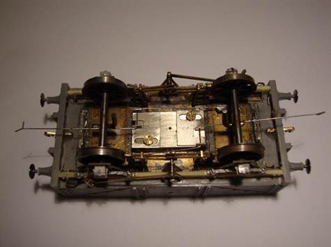
A photograph of a bogie fitted with a hinged AJ is shown above in the section on fitting scratchbuilt hinged AJ’s. Below are two photographs with AJ’s fitted to a Bachmann BR Mark 1 with Bill Bedford sprung bogie units which are shown here for guidance only.
A photograph of a bogie fitted with a hinged AJ is shown above in the section on fitting scratchbuilt hinged AJ’s. Below are two photographs with AJ’s fitted to a Bachmann BR Mark 1 with Bill Bedford sprung bogie units which are shown here for guidance only.
 The first shows a bogie with a fixed AJ
The second shows the other bogie with a coil sprung coupling fitted as designed by John Crompton and described on Pages 49 and 50 of the Alex Jackson Book. It should be noted that this still requires a dropper to be fitted to the model.
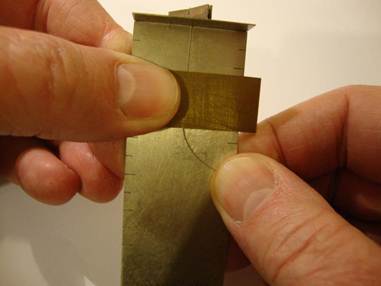
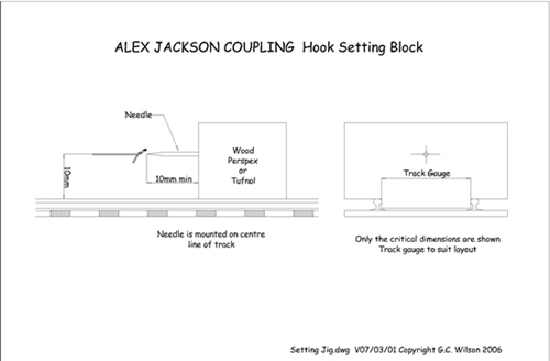
Hook setting gauge
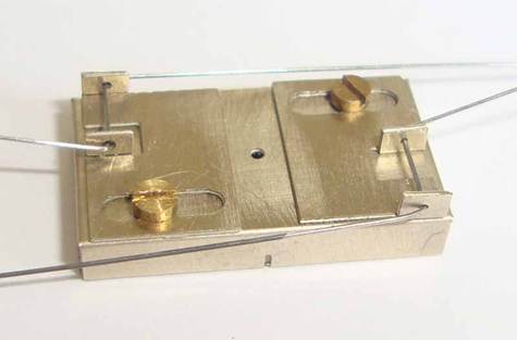
The shank height – i.e. the normal height of the wire above the top surface of the rail – is, at 10mm, one of the important dimensions which must be used at all times to ensure consistency of operation. Another important rule is that the wire must lie along the centre line of the track. It therefore follows that it must lie along the longitudinal centre line of the vehicle. Both conditions can easily be set and maintained by use of the simple hook setting gauge shown below and this is the only way that such a check should be made; setting one coupling against another will only compound any errors made.
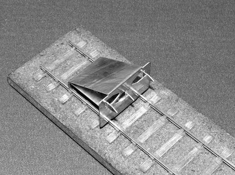
Homemade gauges can be fabricated from materials often found in a modeller’s scrap box. The one above is made from two scraps of brass held together with OO frame spacers. A commercially available jig by Morgan Gilbert, shown below, is available through various outlets including the Scalefour Society. This jig also gauges the correct height for buffers.
Click here to view part 4